¶ Temp Calibration
In FDM 3D printing, the temperature is a critical factor that affects the quality of the print. There is no other calibration that can have such a big impact on the print quality as temperature calibration.
Nozzle Temp tower
Nozzle temperature is one of the most important settings to calibrate for a successful print. The temperature of the nozzle affects the viscosity of the filament, which in turn affects how well it flows through the nozzle and adheres to the print bed. If the temperature is too low, the filament may not flow properly, leading to under-extrusion, poor layer adhesion and stringing. If the temperature is too high, the filament may degrade, over-extrude and produce stringing.
/resource/pictures/orca-flashforge/tem.mp4
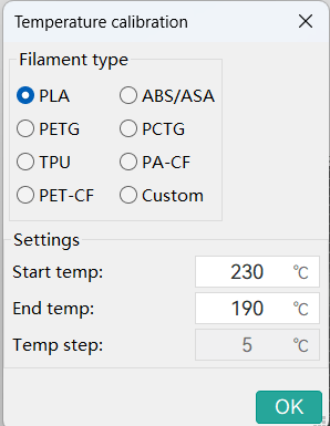
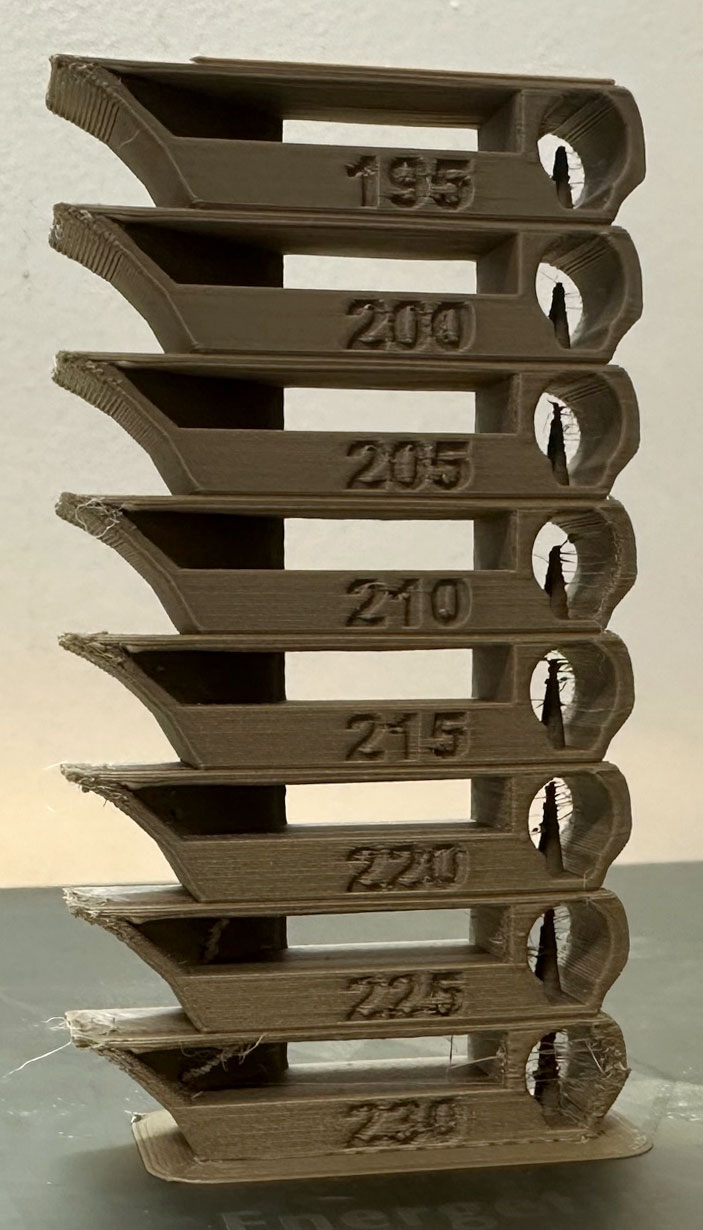
Temp tower is a straightforward test. The temp tower is a vertical tower with multiple blocks, each printed at a different temperature.
Once the print is complete, we can examine each block of the tower and determine the optimal temperature for the filament. The optimal temperature is the one that produces the highest quality print with the least amount of issues, such as stringing, layer adhesion, warping (overhang), and bridging.
Note
If a range of temperatures looks good, you may want to use the middle of that range as the optimal temperature.
But if you are planning to print at higher speeds/flow rates, you may want to use the higher end of that range as the optimal temperature.
For detailed information, please visit official website.
¶ Pressure Advance
Pressure Advance calibration helps compensate for the lag in extrusion pressure that occurs when the print head changes speed. Properly calibrated Pressure Advance can significantly improve print quality, especially during rapid acceleration and deceleration.
OrcaSlicer includes three approaches for calibrating the Pressure Advance value. Each method has its own advantages and disadvantages. It is important to note that each method has two versions: one for a direct-drive extruder and one for a Bowden extruder. Make sure to select the appropriate version for your test.
Calibration
You can use different methods to calibrate the Pressure Advance value, each with its own advantages and disadvantages.
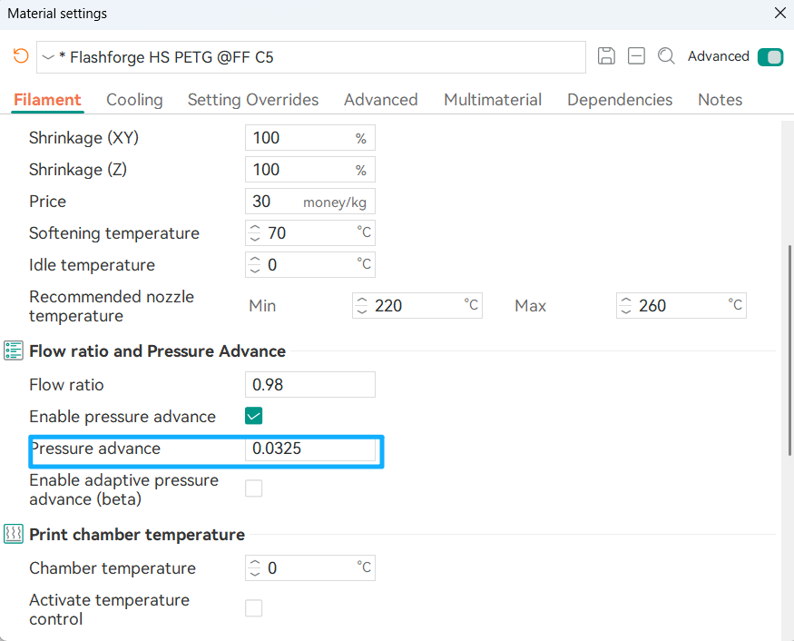
The results from these methods should be saved to the material profile.
1.Tower method
The tower method may take a bit more time to complete, but it does not rely on the quality of the first layer.
Select the printer, filament, and process you would like to use for the test.
Examine each corner of the print and mark the height that yields the best overall result.
In this example a height of 8 mm was selected, so the Pressure Advance value should be calculated as:
PressureAdvanceStart + (PressureAdvanceStep x measured); example: 0 + (0.002 x 8) = 0.016.
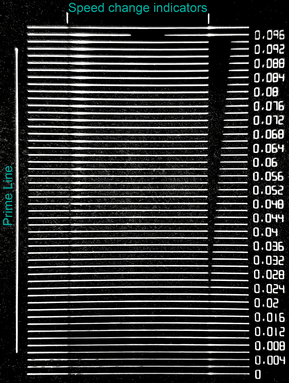
2.Line method
The line method is quick and straightforward to test. However, its accuracy depends heavily on the quality of your first layer. It is suggested to turn on bed mesh leveling for this test.
steps:
Select the printer, filament, and process you would like to use for the test.
Print the project and check the result. Choose the value corresponding to the most even line and update your Pressure Advance value in the filament settings.
In this test, a Pressure Advance value of 0.016 appears to be optimal.
For detailed information, please visit official website.
¶ Flow Rate Calibration
Flow ratio determines how much filament is extruded and is crucial for high-quality prints.
A properly calibrated flow ratio ensures consistent layer adhesion and accurate dimensions.
Too low flow ratio causes under-extrusion, which leads to gaps, weak layers, and poor structural integrity.
Too high flow ratio causes over-extrusion, resulting in excess material, rough surfaces, and dimensional inaccuracies.
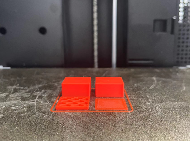
This example uses the Monotonic Line pattern with the 2-Pass Calibration approach.
- Select the printer, filament, and process you want to use for the test.
- In the Calibration menu, under the Flow Rate section, select Pass 1.
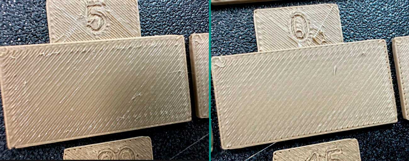
- A new project with nine blocks will be created, each with a different flow rate modifier. Slice and print the project.
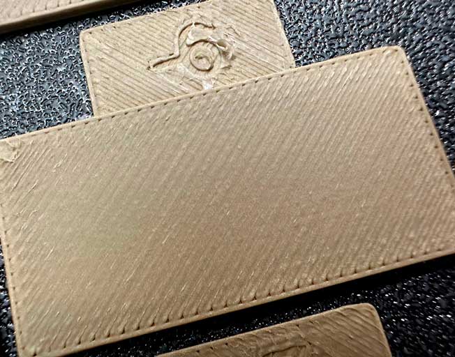
- Examine the blocks and determine which one has the smoothest top surface.
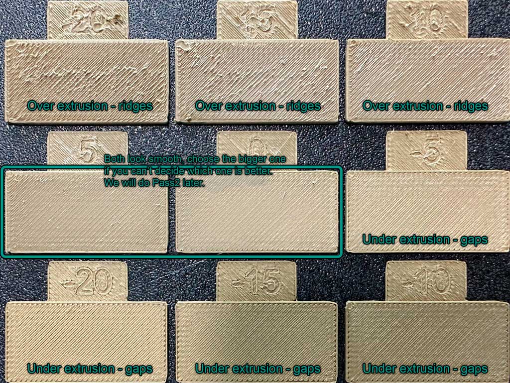
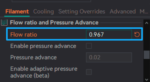
- Update the flow ratio in the filament settings using the equation: OldFlowRatio * (100 + modifier) / 100. For example, if your previous flow ratio was 0.98 and you selected the block with a flow rate modifier of +5, the new value would be: 0.98 × (100 + 5) / 100 = 1.029. Remember to save the filament profile.
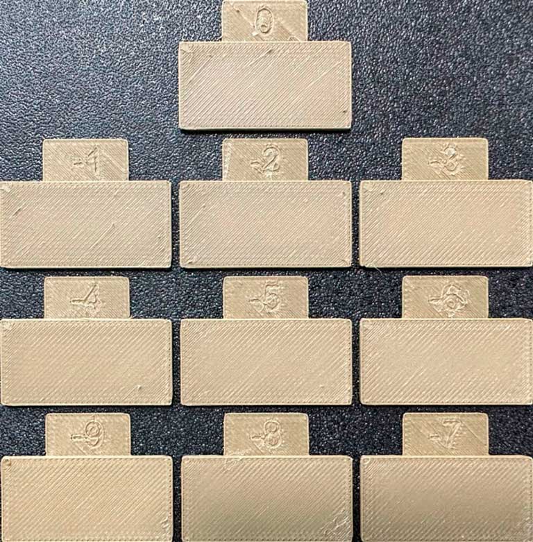
- Perform the Pass 2 calibration. This process is similar to Pass 1, but a new project with ten blocks will be generated. The flow rate modifiers for this project will range from -9 to 0.
- Repeat steps 4 and 5. For example, if your previous flow ratio was 1.029 and you selected the block with a flow rate modifier of -6, the new value would be: 1.029 × (100 - 6) / 100 = 0.96726. Remember to save the filament profile.
¶ retraction calib
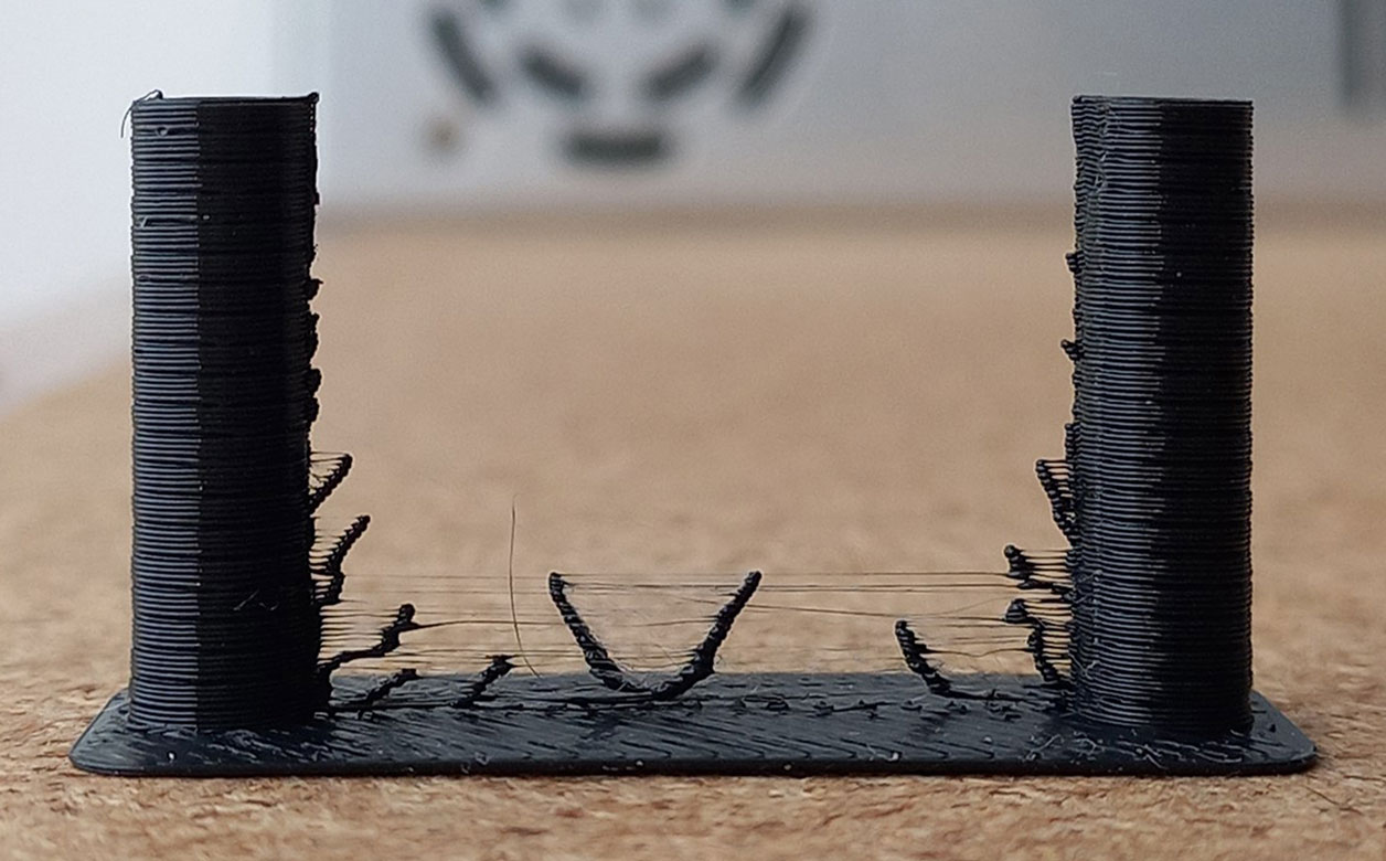
This Retraction test generates a retraction tower automatically. The retraction tower is a vertical structure with multiple notches, each printed at a different retraction length. After the print is complete, we can examine each section of the tower to determine the optimal retraction length for the filament. The optimal retraction length is the shortest one that produces the cleanest tower.
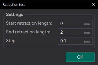
In the dialog, you can select the start and end retraction length, as well as the retraction length increment step. The default values are 0mm for the start retraction length, 2mm for the end retraction length, and 0.1mm for the step. These values are suitable for most direct drive extruders. However, for Bowden extruders, you may want to increase the start and end retraction lengths to 1mm and 6mm, respectively, and set the step to 0.2mm.
Note
When testing filaments such as PLA or ABS that have minimal oozing, the retraction settings can be highly effective. You may find that the retraction tower appears clean right from the start. In such situations, setting the retraction length to 0.2mm - 0.4mm using OrcaSlicer should suffice. On the other hand, if there is still a lot of stringing at the top of the tower, it is recommended to dry your filament and ensure that your nozzle is properly installed without any leaks.
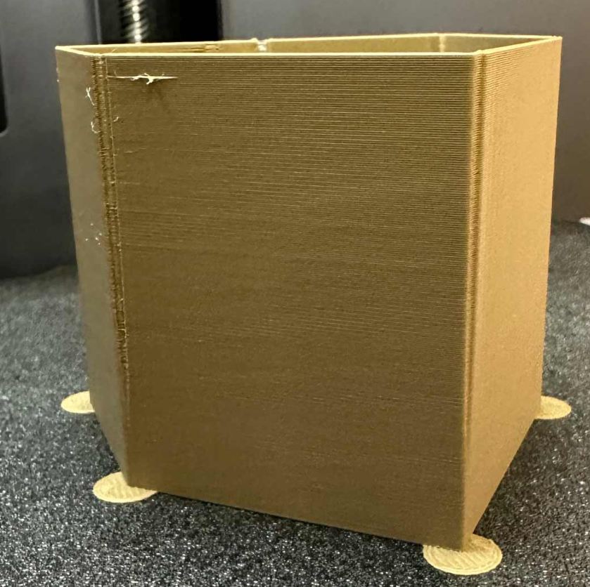
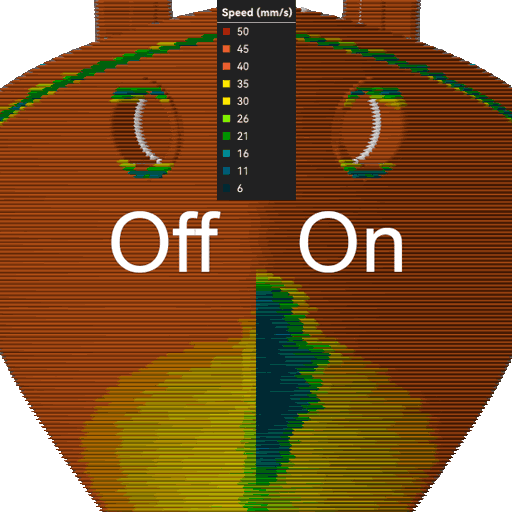
¶ Max Volumetric Speed (FlowRate) Calibration
Max Volumetric Speed value varies depending on your material, machine, nozzle diameter, and even your extruder setup, so it’s important to calibrate it for your specific printer and each filament you use.
Note
Even for the same material type (e.g., PLA), the brand and color can significantly affect the maximum flow rate.
Tip
If you're planning to increase speed or flow, it’s a good idea to increase your nozzle temperature, preferably toward the higher end of the recommended range for your filament. Use a temperature tower calibration to find that range.
Calibration Overview
You will be prompted to enter the settings for the test: start volumetric speed, end volumetric speed, and step. It is recommended to use the default values (5mm³/s start, 20mm³/s end, with a step of 0.5), unless you already have an idea of the lower or upper limit for your filament. Select "OK", slice the plate, and send it to the printer.
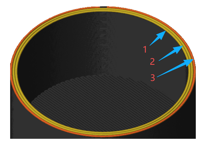
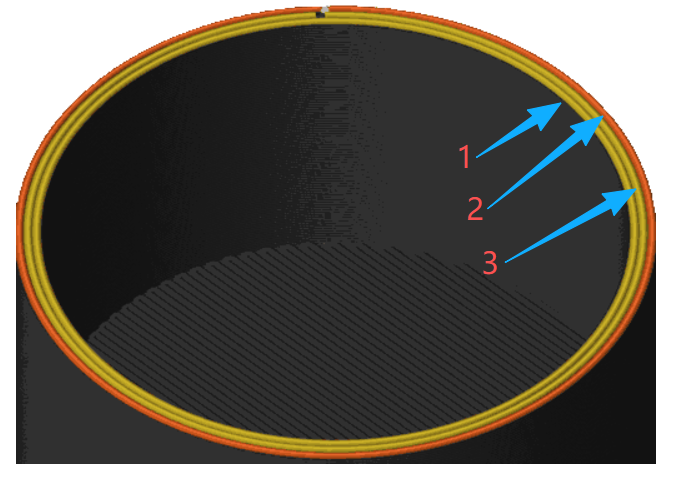
Once printed, take note of where the layers begin to fail and where the quality begins to suffer.
Tip
A change in surface sheen (glossy vs. matte) is often a visual cue of material degradation or poor layer adhesion.
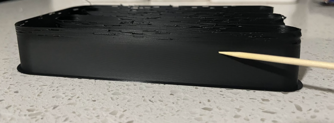
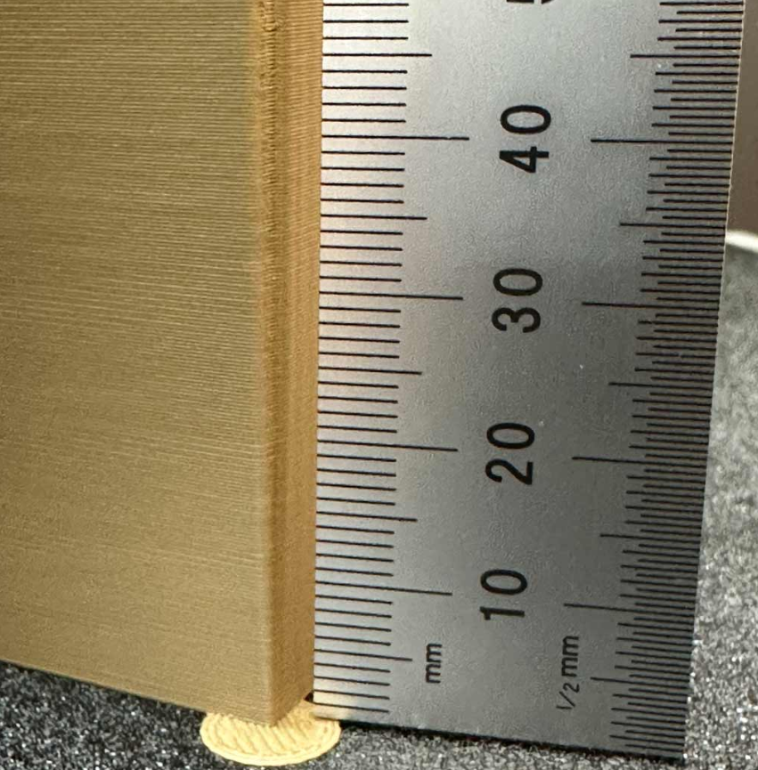
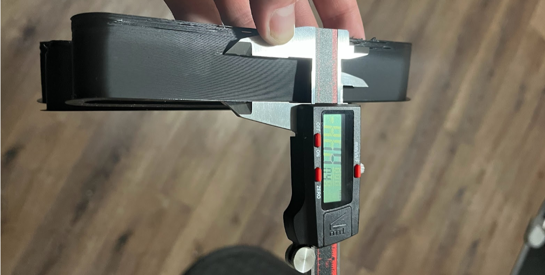
Use calipers or a ruler to measure the height of the model just before the defects begin.
Then you can:
Use the following formula:
FilamentMaxVolumetricSpeed】=start+(HeightMeasured∗step)
In this case (19mm), so the calculation would be: 5 + (19 * 0.5) = 14.5mm³/s
Use OrcaSlicer in the "Preview" tab, make sure the color scheme "flow" is selected. Scroll down to the layer height that you measured, and click on the toolhead slider. This will indicate the max flow level for your filament.
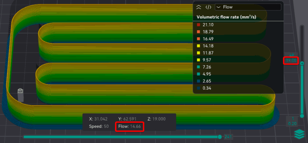
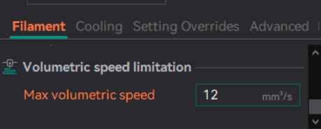
After you have determined the maximum volumetric speed, you can set it in the filament settings. This will ensure that the printer does not exceed the maximum flow rate for the filament.
Note
This test is a best case scenario and doesn't take into account Retraction or other settings that can increase clogs or under-extrusion.
You may want to reduce the flow by 10%-20% (or even further) to ensure print quality/strength.
Printing at high volumetric speed can lead to poor layer adhesion or even clogs in the nozzle.
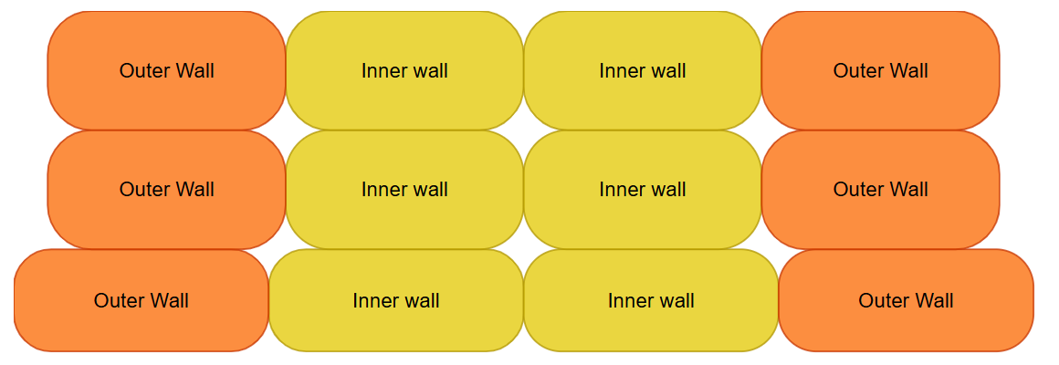
¶ Walls printing order
Print sequence of the internal (inner) and external (outer) walls.
Inner/Outer
Use Inner/Outer for best overhangs. This is because the overhanging walls can adhere to a neighboring perimeter while printing. However, this option results in slightly reduced surface quality as the external perimeter is deformed by being squashed to the internal perimeter.
Inner/Outer/Inner
Use Inner/Outer/Inner for the best external surface finish and dimensional accuracy as the external wall is printed undisturbed from an internal perimeter. However, overhang performance will reduce as there is no internal perimeter to print the external wall against. This option requires a minimum of 3 walls to be effective as it prints the internal walls from the 3rd perimeter onwards first, then the external perimeter and, finally, the first internal perimeter. This option is recommended against the Outer/Inner option in most cases.
Outer/Inner
Use Outer/Inner for the same external wall quality and dimensional accuracy benefits of Inner/Outer/Inner option. However, the z seams will appear less consistent as the first extrusion of a new layer starts on a visible surface.
¶ Arc fitting
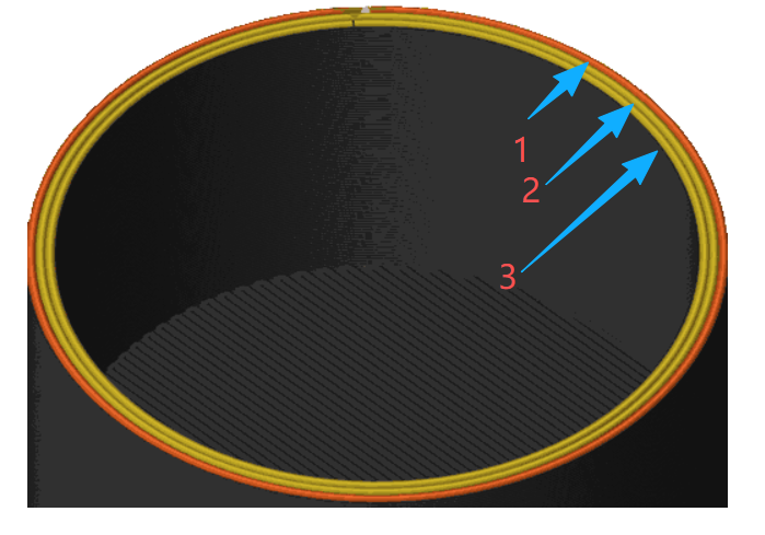
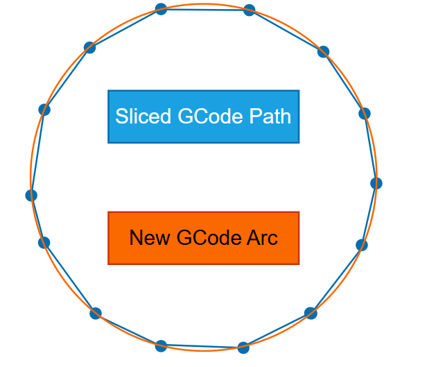
Enable this feature to replace many short straight moves (G1 segments) with fewer circular arc commands using G2 and G3.
Arc fitting mainly changes how the toolpath is encoded in G-code. It can be beneficial in some workflows, but it is not a feature to improve quality .
Important
Ensure that the printer supports G2/G3 commands!
Advantages
- Smaller G-code files:
- Faster upload.
- Less storage usage.
- Reduces the amount of read/writes done in memory and makes an SD card consume less of its already limited TBW.
- Fewer moves for the firmware planner to process:
- Help on slower controllers when doing simultaneous task like save the status for Power Loss Recovery.
- Help limited connections.
- Smoother curves when using a low poly model.
Disadvantages / risks - Compatibility varies: some firmwares ignore G2/G3.
- Arcs introduce approximation: converting segments → arcs in OrcaSlicer and arcs → segments in firmware can slightly change the path.
- The final smoothness depends on the firmware's arc segmentation resolution; coarse settings can make curves look faceted.
- Arc-to-segment conversion increases CPU load on the printer, which can cause slow-downs (and reduced surface quality) on older/8-bit microcontrollers.
Additionally, modern STLs often have a higher resolution than the segments generated by most printer firmwares.
Tip
For Klipper printers see the Support for gcode arc (G2/G3) commands's documentation for setting the resolution of the arcs generated internally: the default is 1.0 mm per segment, which is very rough.
For Marlin printers, you can adjust the variables under #define ARC_SUPPORT in Configuration_adv.h.
Warning
The internal generation of segments from arcs requires higher CPU usage from the printer microcontroller and therefore it might cause slow-downs (and reduced surface quality) on printers using 8-bit microcontrollers.
¶ Elephant foot compensation
This feature compensates for the "elephant foot" effect, which occurs when the first few layers of a print are wider than the rest due:
- Weight of the material above them.
- Thermal expansion of the material.
- Bed temperature being too high.
- Inaccurate bed height/Leveling.
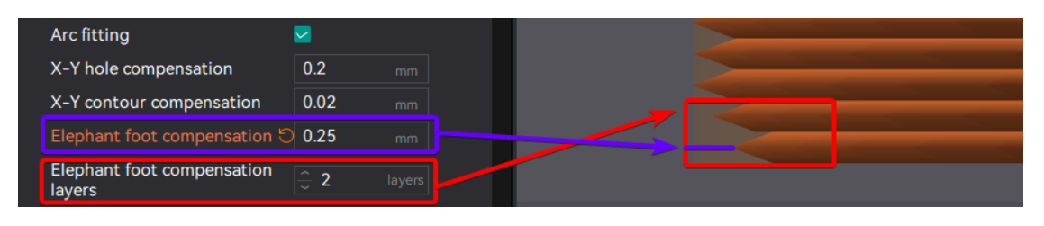
To mitigate this effect, OrcaSlicer allows you to specify a negative distance that will be applied to the first specified number of layers. This adjustment effectively reduces the width of the first few layers, helping to achieve a more accurate final print size.
The compensation works as follows:
When the current_layer is <= input_compensation_layers
compensation = input_compensation_distance - (input_compensation_distance / input_compensation_layers) × (current_layer - 1)
According to the equation, we can establish the following rules: - In the 1st layer, since it is layer 1 - 1 = 0, compensation is 100%.
- The intermediate layers (between the first and input_compensation_layers) will have linear compensation.
- Layers above the specified amount will not be compensated.
Assuming the compensation value is 0.25 mm:
Elephant Foot Compensation Layers = 1 :
- 1st layer: 0.25mm compensation (100%)
- 2nd layer and beyond: No compensation (0 mm)
Elephant Foot Compensation Layers = 2 : - 1st layer: 0.25mm compensation (100%)
- 2nd layer: 0.25 − (0.25 / 2) × (2 - 1) = 0.125mm compensation (50%)
- 3rd layer and beyond: No compensation (0 mm).
Elephant Foot Compensation Layers = 5 : - 1st layer: 0.25mm compensation (100%)
- 2nd layer: 0.25 − (0.25 / 5) × (2 - 1) = 0.2mm compensation (80%)
- 3rd layer: 0.25 − (0.25 / 5) × (3 - 1) = 0.15mm compensation (60%)
- 4th layer: 0.25 − (0.25 / 5) × (4 - 1) = 0.1mm compensation (40%)
- 5th layer: 0.25 − (0.25 / 5) × (5 - 1) = 0.05mm compensation (20%)
- 6th layer and beyond: No compensation (0 mm).
Note
This feature will look like the part have a smaller footprint on the build plate in the preview, but the final print (if calibrated correctly) will have the correct dimensions after slicing.
That's why the Brim may look disconnected from the object when this feature is enabled. But in the final print, the brim will be correctly attached to the object.
If you use a high value for the Elephant Foot Compensation Distance, you may want to enable the Brim use EFC outline option to ensure proper brim attachment.
¶ Slow down for overhang
Enable this option to slow printing down for different overhang degree. This can help improve print quality and reduce issues like stringing or sagging.
¶ Slow down for curled perimeters
Enable this option to slow down printing in areas where perimeters may have curled upwards. For example, additional slowdown will be applied when printing overhangs on sharp corners like the front of the Benchy hull, reducing curling which compounds over multiple layers.
It is generally recommended to have this option switched on unless your printer cooling is powerful enough or the print speed slow enough that perimeter curling does not happen. If printing with a high external perimeter speed, this parameter may introduce slight artifacts when slowing down due to the large variance in print speeds. If you notice artifacts, ensure your pressure advance is tuned correctly.
Note
When this option is enabled, overhang perimeters are treated like overhangs, meaning the overhang speed is applied even if the overhanging perimeter is part of a bridge. For example, when the perimeters are 100% overhanging, with no wall supporting them from underneath, the 100% overhang speed will be applied.
¶ Exclude Objects
This function is applicable when printing multiple models. Its purpose is to allow users to easily select a model to be excluded if it encounters an error during the printing process, ensuring that other models can be printed normally.
Slicing Settings
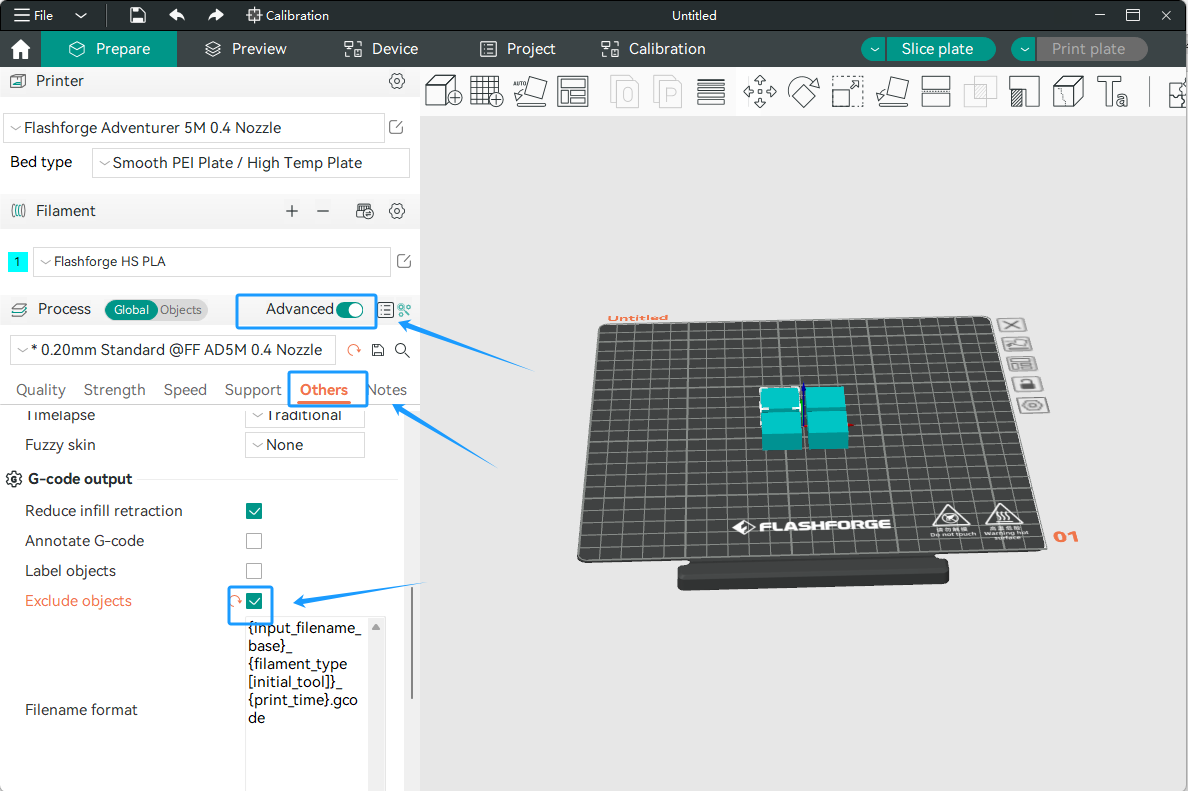
1. First, enable [Advanced] in the process bar. Then check [Exclude objects] on the others page.
2. Slice and print.
Printer Settings
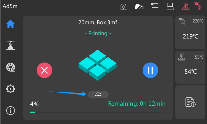
¶ 1. After printing starts, the [ ] icon will appear on the screen. Click it as needed.
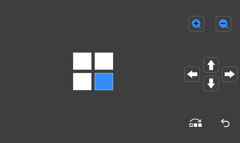
¶ 2. Click [] to enter the exclude objects interface, as explained in the following picture:
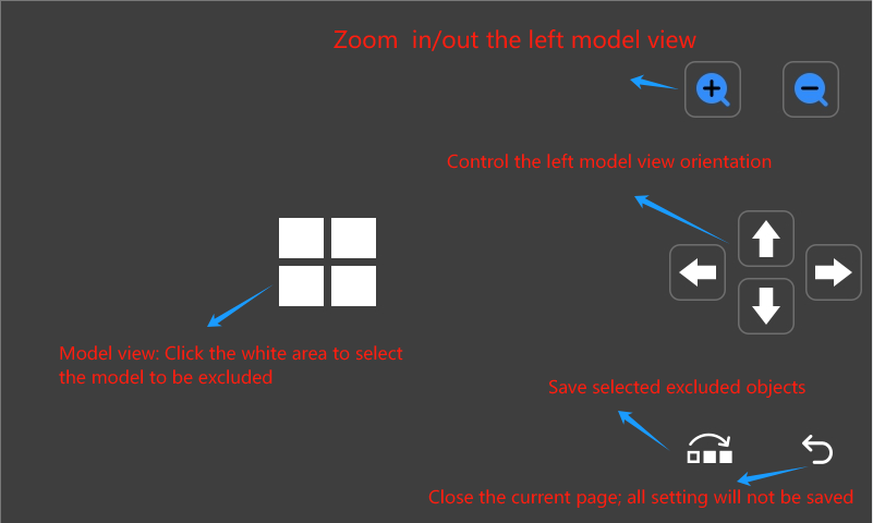
¶ 3. Select the model to be excluded.
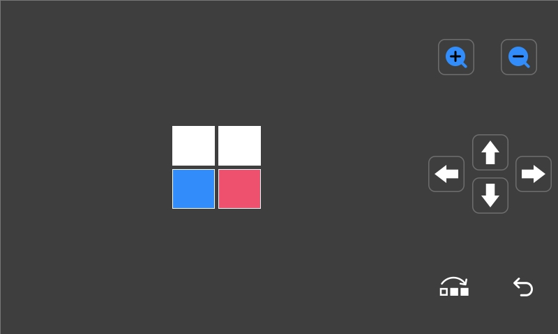
a. Select the model view, click the model to be excluded, and the selected area will be displayed in blue. Click [], and this function will take effect.
b. If you click the wrong area when selecting the model, you can click [![]() ] to reset.
] to reset.
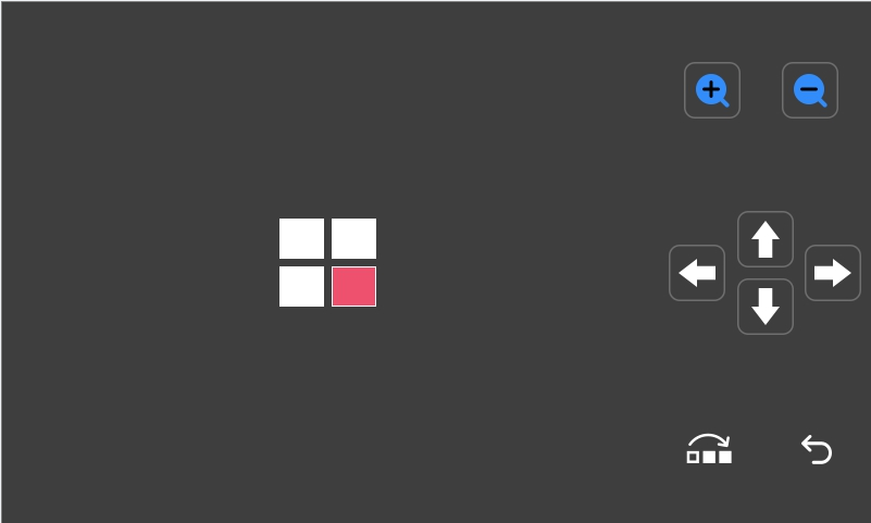
c. After successful saving, the excluded area will be displayed in red.
¶ 4. To select other areas during printing, repeat the above steps.
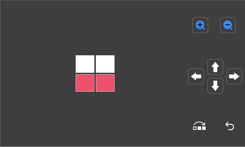
¶ 5. Print result with the [Exclude objects] function enabled: