¶ Infill
In Flash Studio Desktop, infill settings are core controls for managing print quality, strength, and surface finish. A well-tuned infill configuration balances print time, filament usage, and model performance.
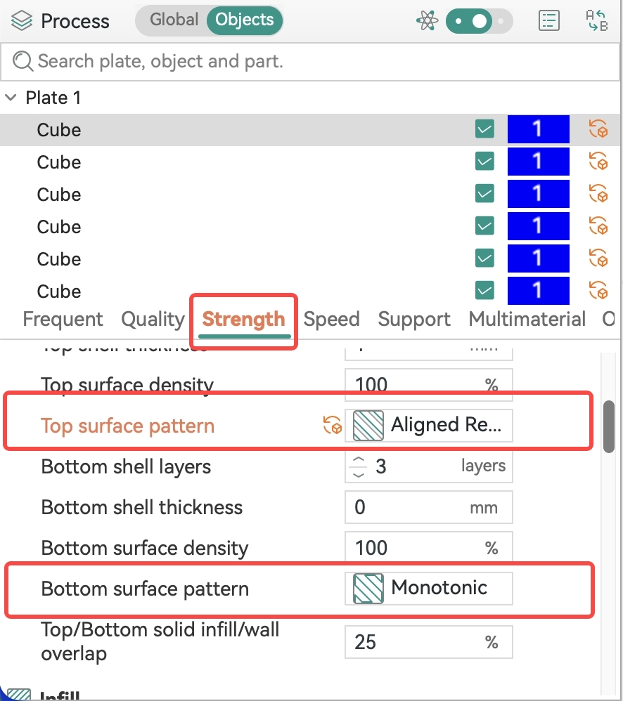 Top/Bottom Pattern |
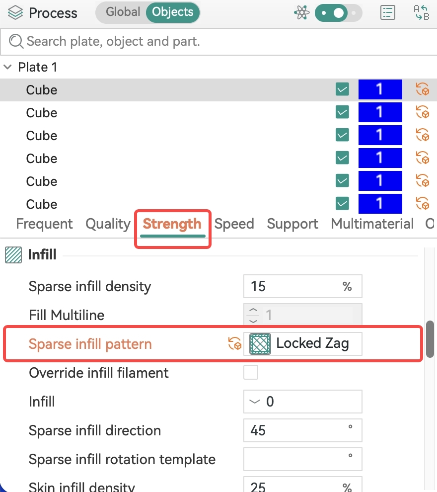 Sparse Infill Pattern |
¶ Sparse Infill
Sparse infill is the internal support structure of a model, with density typically ranging from 5% to 100%. Lower infill density makes the model lighter, uses less filament, and prints faster, but also reduces strength.
Besides density, the choice of infill pattern is equally important. Flash Studio Desktop offers a variety of infill patterns, each differing in directional strength, flexibility, and print speed.
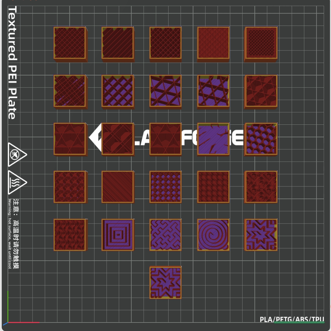
¶ Sparse Infill Patterns
¶ Lines
Consists of parallel straight lines, providing support in only one direction. Fastest print speed, but strength is highly directional — stronger parallel to the lines and weaker perpendicular to them.
Recommended for: Display models or prototype validation where strength is not critical and fast prototyping is the priority.
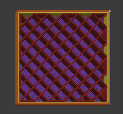
¶ Line Arrangement
Multiple parallel lines arranged at regular intervals. Similar to Lines but with more uniform spacing, suitable for applications requiring even support.
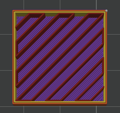
¶ Zigzag
Lines follow a continuous zigzag path with alternating directions between adjacent layers. Provides better inter-layer bonding than the Lines pattern and slightly higher strength.
Recommended for: Parts that need fast printing with moderate strength requirements.
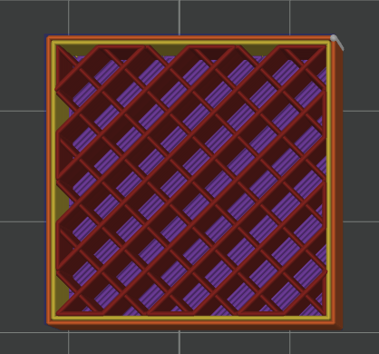
¶ Cross Zigzag
Builds on the Zigzag pattern by adding cross lines to form a cross-hatched grid structure, offering higher strength than standard Zigzag.
Recommended for: General-purpose parts requiring higher strength with fast print speed.
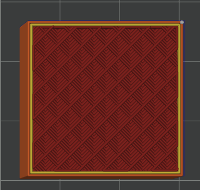
¶ Bounded Zigzag
Constrains the Zigzag pattern within boundaries, making the infill conform more closely to the model outline and reducing edge gaps.
Recommended for: Parts with high requirements for inner wall conformity.
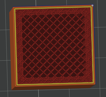
¶ Line
Single-layer continuous line infill. Similar to Lines but with a different path strategy, suitable for thin-wall structures.
¶ Grid
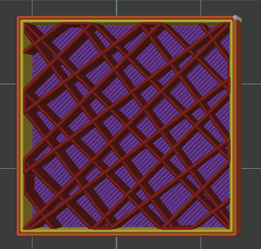
Composed of mutually intersecting straight lines forming a square grid. Provides balanced strength in both X and Y directions. Prints with alternating layer directions for good inter-layer bonding.
Recommended for: General structural parts requiring balanced strength in all directions.
¶ Triangles
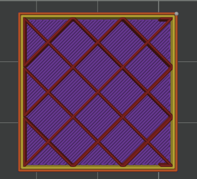
Formed by lines interweaving in three directions to create a triangular grid. Triangles are the most stable geometric structure, providing excellent multi-directional strength in the X-Y plane.
Recommended for: Functional parts subject to multi-directional stress.
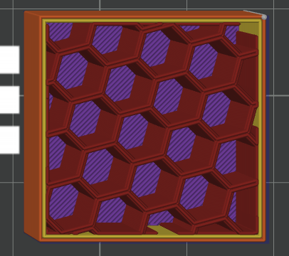
¶ Inside Hexagon
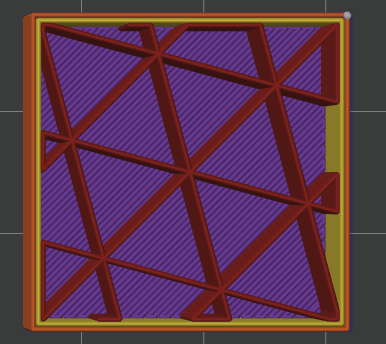
A hexagonal honeycomb-like structure that provides good planar strength while keeping weight low. Continuous lines ensure smooth printing.
Recommended for: Parts that need to be lightweight yet maintain moderate strength.
¶ Cubic
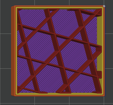
Arranged along three axes in 3D space to form a cubic structure. Provides uniform strength in all directions with strong inter-layer bonding.
Recommended for: Functional parts with high overall strength requirements.
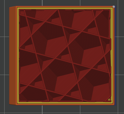
¶ Adaptive Cubic
An improved version of Cubic that adaptively adjusts infill density based on model geometry — automatically increasing density in high-stress areas and reducing it in non-critical zones.
Recommended for: Functional parts where optimizing the strength-to-weight ratio is important.
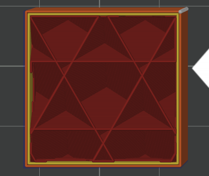
¶ Quarter Cubic
A variant of the Cubic structure with lower line density, faster print speed, and slightly lower strength than standard Cubic.
Recommended for: Parts with moderate strength requirements where faster print speed is desired.
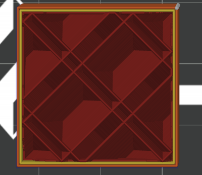
¶ Support Cubic
Builds on the Cubic pattern by adding extra support lines to improve overall structural stability.
Recommended for: Large-scale parts requiring high structural stability.
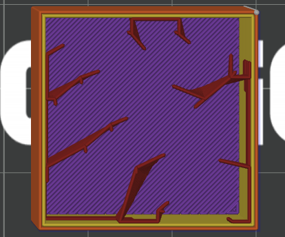
¶ Lightning
Generates support structures only beneath top surfaces, leaving the interior completely hollow. Significantly saves filament and time, but only provides top-side support.
Recommended for: Display or decorative models that do not require internal strength.
¶ Honeycomb
A planar hexagonal honeycomb structure — a classic lightweight pattern that provides good planar strength for the same amount of filament.
Recommended for: Parts requiring lightweight construction with good planar strength.
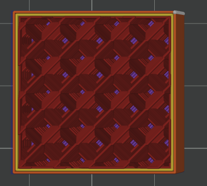
¶ 3D Honeycomb
A 3D extension of the Honeycomb structure that also provides support in the Z direction, offering better overall strength than planar honeycomb.
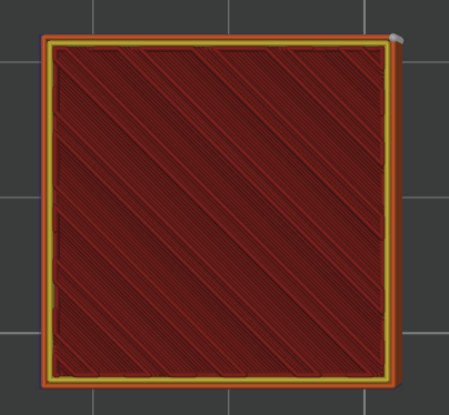
¶ Lateral Honeycomb
Honeycomb structure arranged laterally, suitable for parts subject to lateral stress.
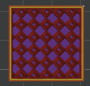
¶ Cross Hatch
Multiple layers of intersecting lines forming a dense mesh structure with high strength.
Recommended for: Parts requiring high planar strength.
¶ TPMS-D / TPMS-FK
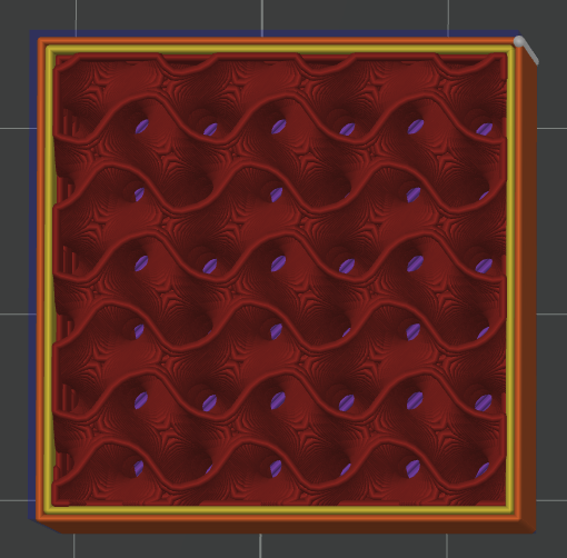
Complex 3D structures based on Triply Periodic Minimal Surfaces (TPMS). TPMS structures provide nearly uniform mechanical performance in all directions with an extremely high strength-to-weight ratio. D and FK are two different surface topology variants.
Recommended for: Engineering parts with demanding mechanical requirements, biomimetic structural components.
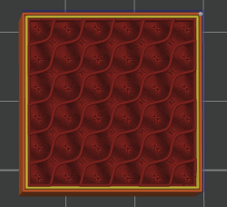
¶ Spiral
Continuous spiral curve infill with no crossing points, ensuring smooth extrusion flow and minimal vibration. Provides nearly uniform strength in all directions.
Recommended for: Parts requiring isotropic strength with weight sensitivity.
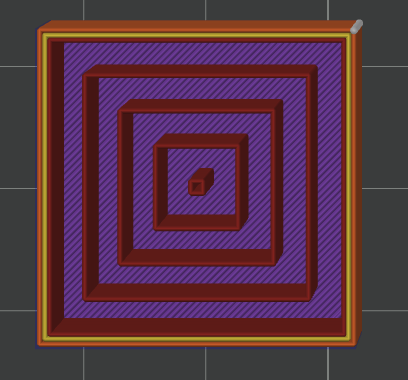
¶ Concentric
Concentric lines shrinking inward from the model outline. Matches the model's outer wall shape, providing support aligned with the wall direction.
Recommended for: Flexible parts or parts that need to deform consistently with the outer wall.
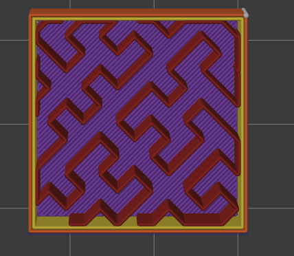
¶ Hilbert Curve
A space-filling fractal curve infill with uniform coverage, no crossing points, and dense structure.
Recommended for: Special parts requiring uniform and dense infill.
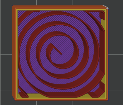
¶ Archimedean Chords
An infill pattern based on Archimedean spiral lines with uniform spacing and a regular structure.
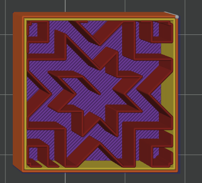
¶ Octagram Spiral
An octagonal spiral infill pattern with interlocking lines forming a stable geometric design.
¶ Sparse Infill Pattern Selection Guide
| Requirement | Recommended Pattern |
|---|---|
| Rapid prototyping | Lines / Lightning |
| Storage boxes, brackets, enclosures | Grid / Zigzag |
| Multi-directional load-bearing parts (clips, hinges, jigs) | Triangles / Cubic |
| Isotropic + lightweight (drone parts, robotic arms) | Spiral / 3D Honeycomb |
| Extreme lightweight (aeromodel parts, display models) | Lightning / Inside Hexagon |
| High engineering strength (gears, load-bearing structures, functional test parts) | TPMS-D / TPMS-FK / Adaptive Cubic |
| Elastic/flexible parts (gaskets, buffers, flexible hinges) | Concentric / Spiral |
¶ Top/Bottom Infill
Top and bottom infill (also called "top/bottom walls") are the solid layers on the upper and lower surfaces of a model. Unlike sparse infill, top/bottom infill consists of dense solid layers that directly determine surface quality.
¶ How It Works
FDM printing builds objects layer by layer. Without enough solid layers on the top and bottom, the sparse infill grid will show through the surface, causing top surface sagging and bottom surface roughness. The role of top/bottom infill is to create a flat, solid transition between the sparse infill and the outer walls, giving the outer surfaces a uniform support base.
- Insufficient top infill layers: Upper lines lack support, causing visible sagging, grid patterns on the surface, and even stringing.
- Insufficient bottom infill layers: The first layer sits directly on the sparse infill cavity, resulting in a rough bottom surface with "ghosting" textures.
¶ Top/Bottom Infill Patterns
Top and bottom infill share the same pattern options. Different patterns affect surface appearance texture and print efficiency.
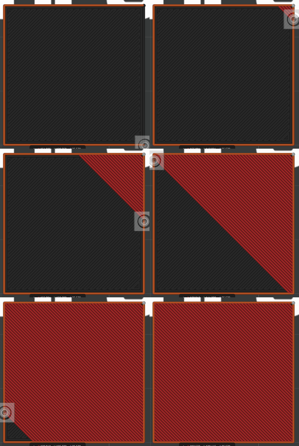
¶ Monotonic
Each infill line starts printing from the same direction, ensuring consistent travel direction across the entire surface. Produces uniform color and texture for the best visual result, though print time is slightly longer.
Recommended for: Display pieces with high appearance requirements, visible surface parts.
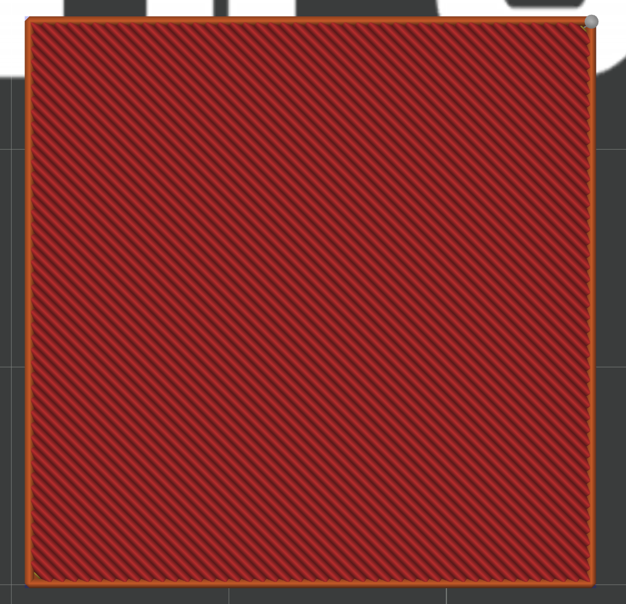
¶ Monotonic Lines
Similar to Monotonic, but only ensures consistent direction within each individual line — different lines may vary in direction. Balances surface quality and print speed.
Recommended for: Default choice for most general-purpose applications.
¶ Lines
Standard parallel line infill with fast print speed. The surface will show noticeable parallel line textures.
Recommended for: Functional parts where surface texture is not a concern.
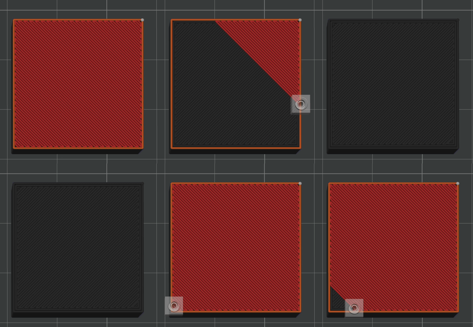
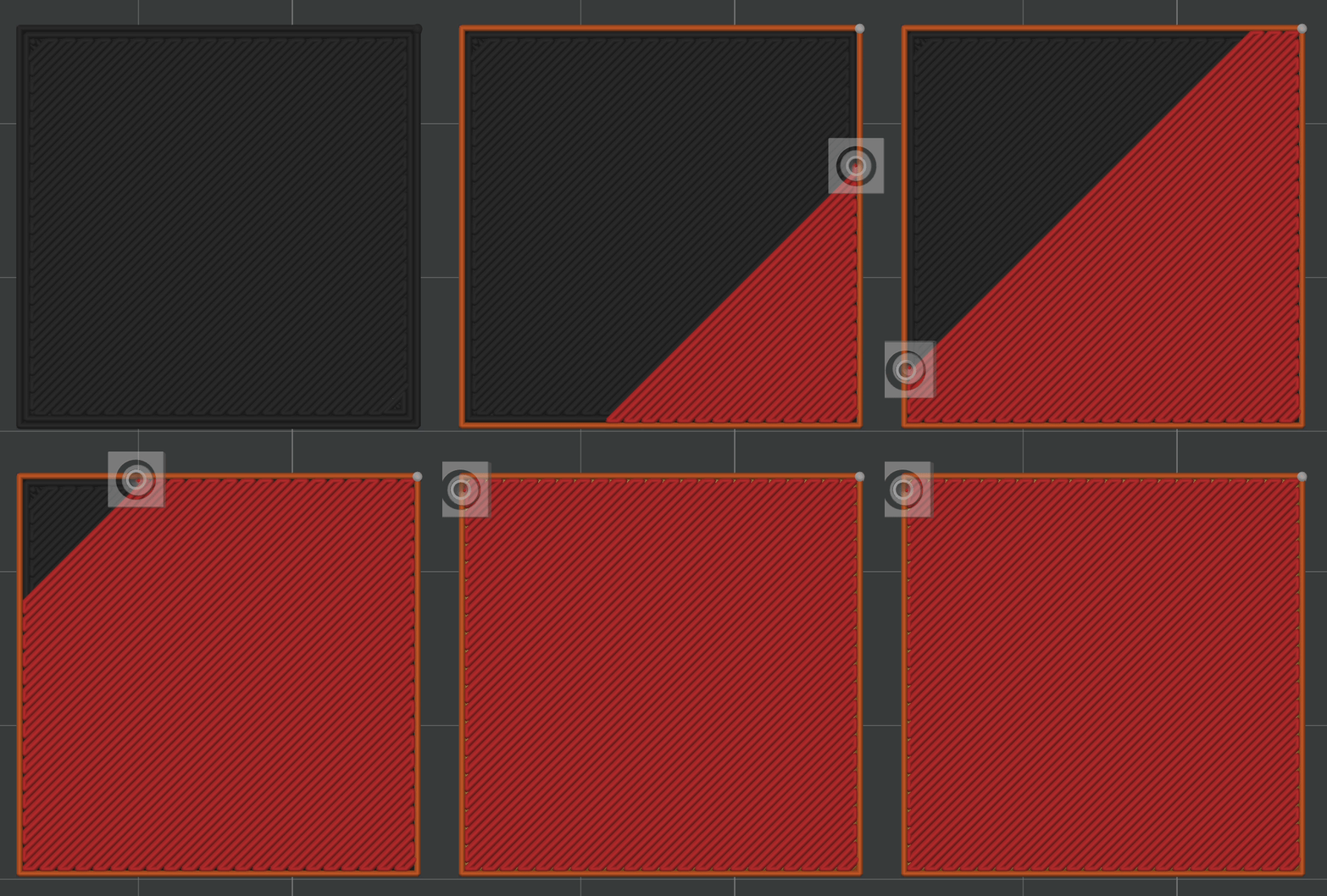
¶ Line Arrangement
Parallel lines arranged at fixed intervals with more uniform texture.
Recommended for: Parts requiring a neat, regular surface texture.
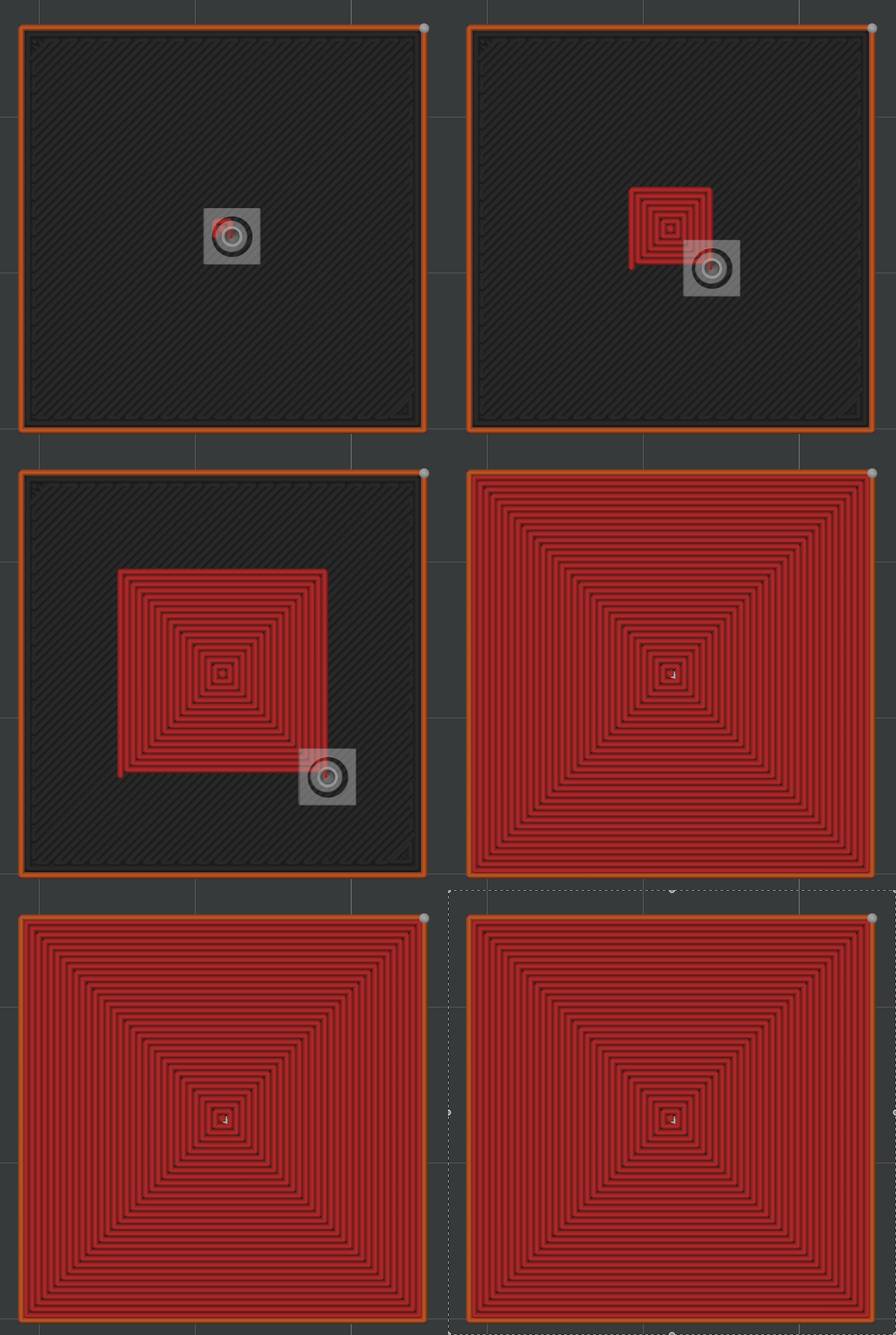
¶ Concentric
Concentric lines shrinking inward from the model outline. Surface texture follows the model contour for a distinctive visual effect.
Recommended for: Parts with personalized surface appearance requirements.
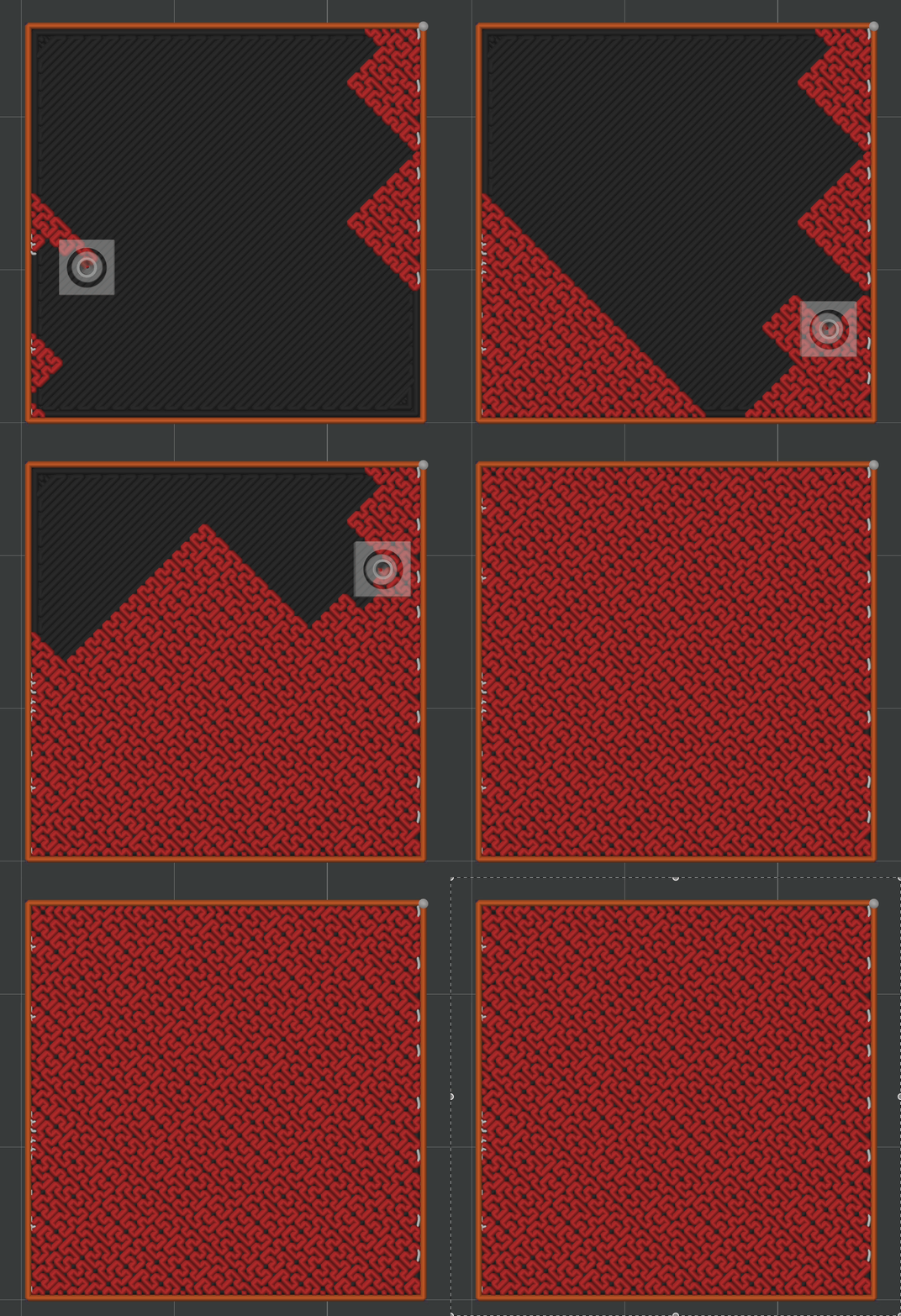
¶ Hilbert Curve
Fractal continuous curve infill producing a fine, uniform surface texture with no directional bias.
Recommended for: Special parts requiring a uniform surface texture.
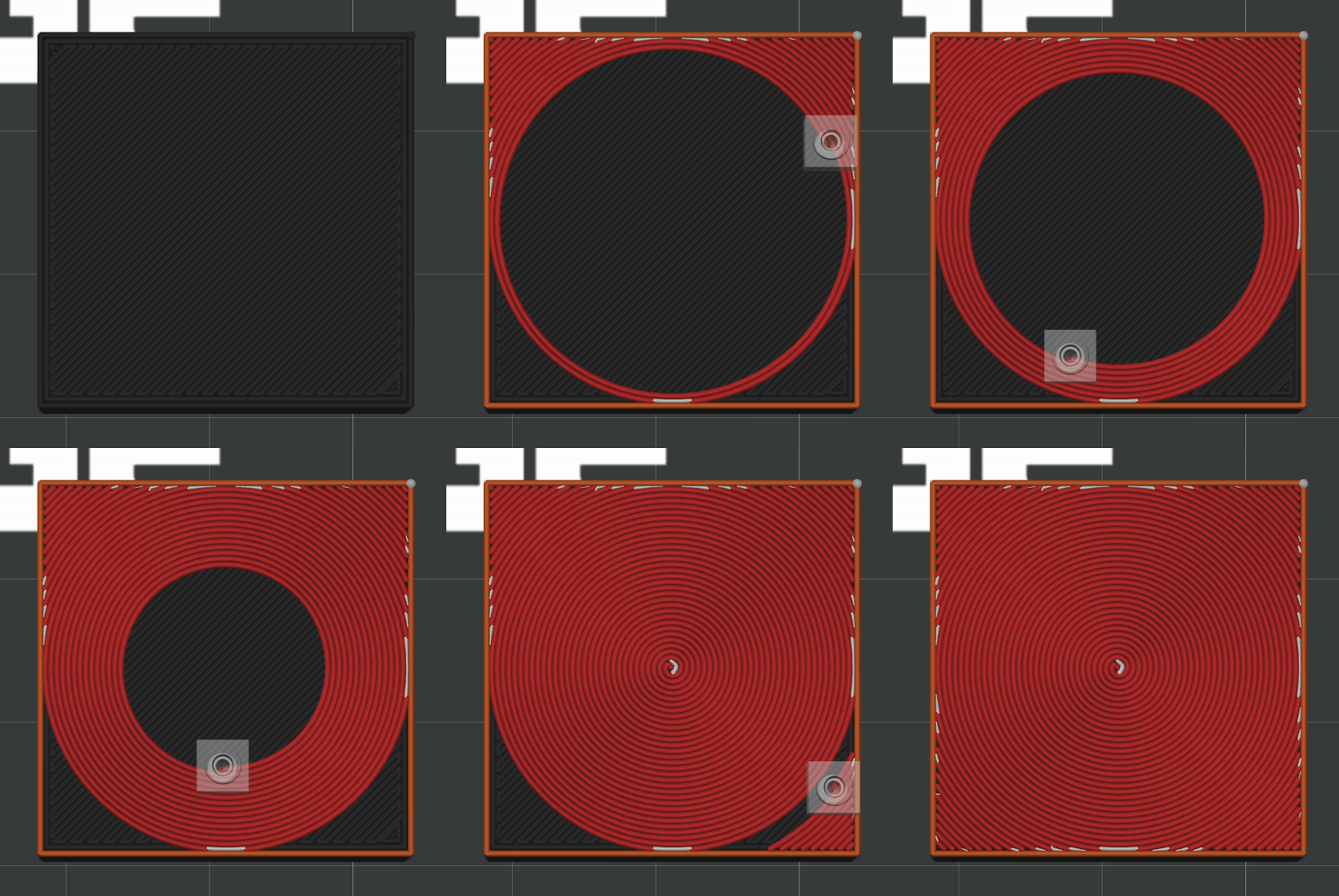
¶ Archimedean Chords
Archimedean spiral-based infill producing a spiral surface texture.
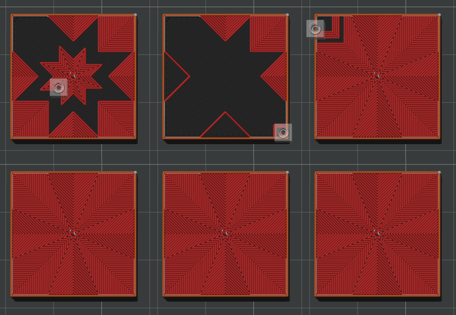
¶ Octagram Spiral
Octagonal spiral infill producing a unique geometric surface texture.
¶ Parameter Description
Top Wall Layers / Bottom Wall Layers
Controls how many solid layers to print on the top and bottom surfaces, measured in layers. More layers produce a flatter surface but increase print time and filament usage.
Top Wall Thickness / Bottom Wall Thickness
Controls the total thickness of the solid layers on the top and bottom surfaces, measured in millimeters. The software automatically calculates the required number of layers based on layer height.
Both methods are essentially equivalent — use whichever you prefer.
¶ Setting Recommendations
- General models: 3–4 layers for both top and bottom (approx. 0.6–0.8mm at 0.2mm layer height), covering most use cases.
- High surface quality (e.g., display pieces, assembly surfaces): Increase to 5–6 layers and use the "Monotonic" pattern to prevent grid patterns from showing through.
- Small models or low-precision prototypes: Can be reduced to 2 layers to save time.
- Bottom surface (bed contact): 3 layers is usually sufficient to ensure a flat bottom.