¶ Print Temperature Calibration
Note: After completing calibration, please be sure to create a new project to reset the slicing software's state.
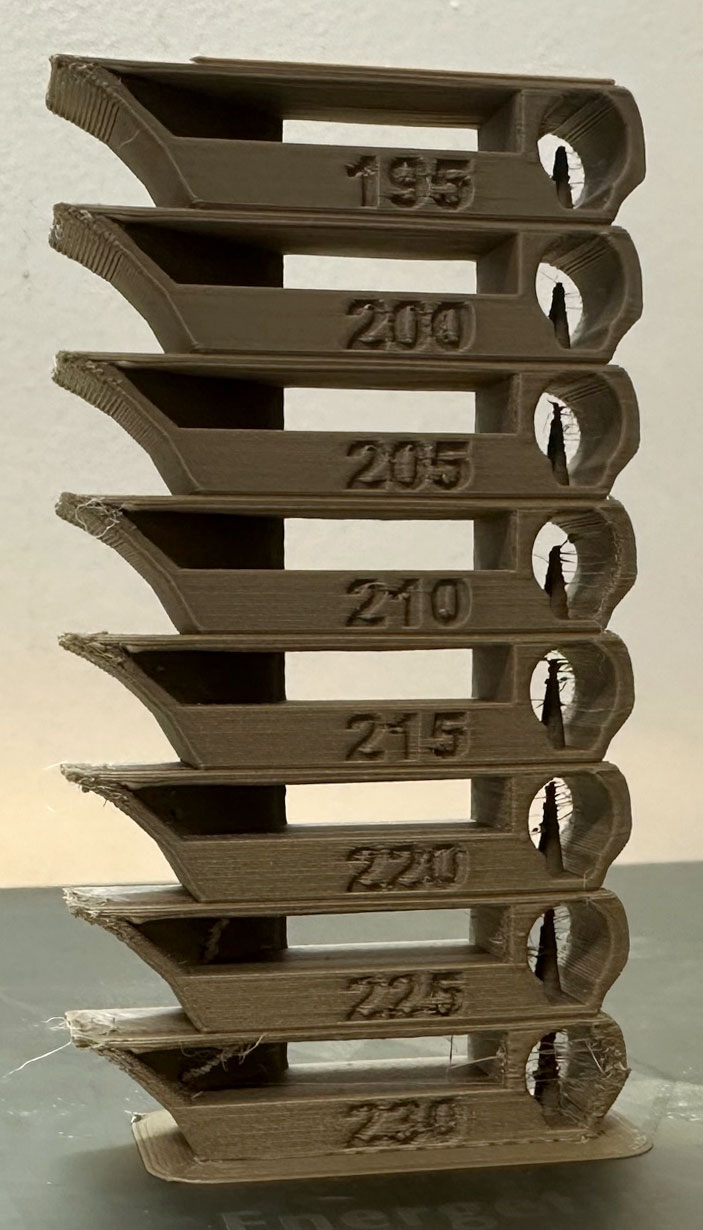
The temperature tower is a very intuitive test. The temperature tower is divided into multiple layers vertically, with each layer printed at a different temperature. We can determine the optimal printing temperature based on the print quality of each layer.
Typically, the optimal temperature will produce layers with less stringing, better layer adhesion, less warping, and better overhang and bridging quality.
For detailed information, please visit the official website (https://gitee.com/n0isyfox/orca-slicer-docs/wikis/校准/温度塔)
¶ Pressure Advance (PA)
Note: After completing calibration, please be sure to create a new project to reset the slicing software's state.
Orca Slicer provides 3 methods for calibrating pressure advance. Each mode has its own advantages and disadvantages. Please note that each mode has two types, corresponding to direct drive (near-close) extruders and Bowden (remote) extruders.
Please be sure to select the corresponding calibration type based on your machine's actual configuration.
1. Line Mode
Line mode is the fastest and most direct method, but the accuracy of the final result heavily depends on your printer's first layer print quality. It is strongly recommended to enable the printer's bed leveling function when using this mode.
The test steps for this mode are as follows:
Select the printer, filament, and process you want to calibrate.
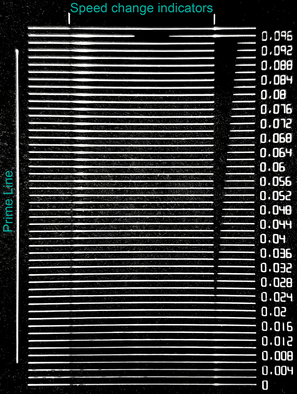
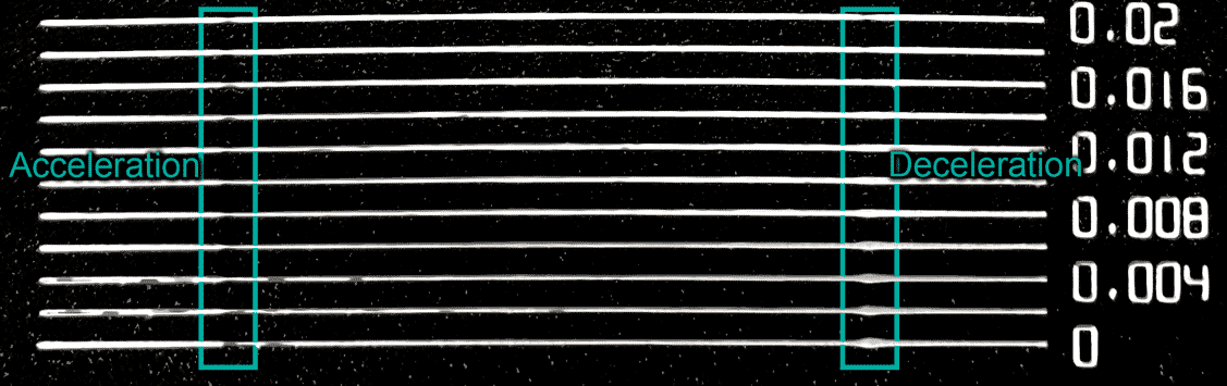
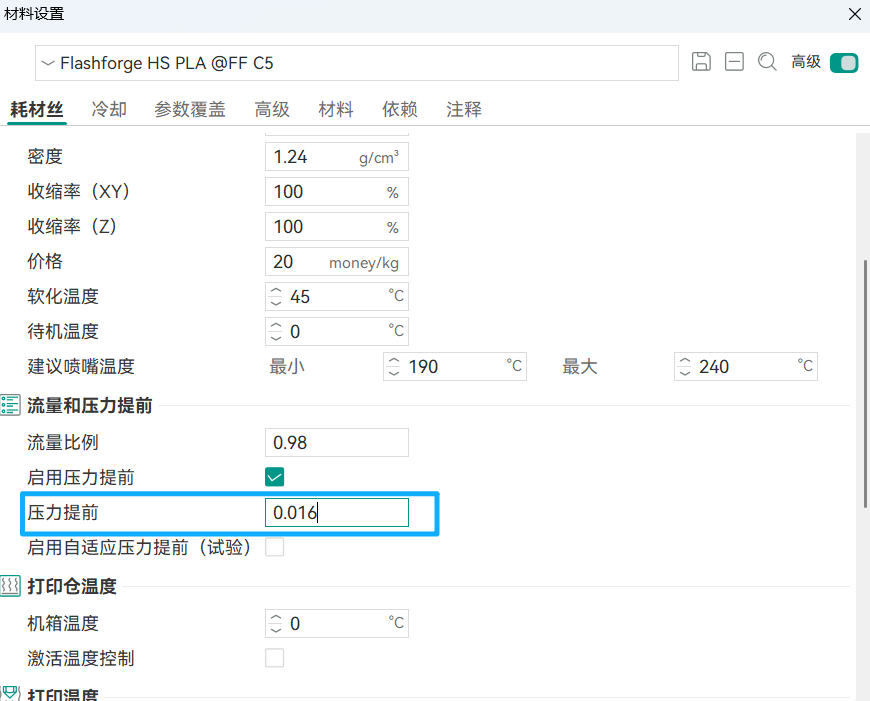
Print the project and observe the results yourself. Select the number corresponding to the line that appears most uniform — that is the optimal PA value. Enter this value in the pressure advance option in the filament settings.
For example, based on the results shown in the image below, the optimal PA value is 0.016:
2. PA Tower
PA Tower mode takes longer to test, but it is not affected by first layer quality. For direct drive extruder testing, the PA tower increases the PA value by 0.002 for every 1mm printed; for Bowden extruders, the PA value increases by 0.02 per 1mm.
The test steps for this mode are as follows:
Select the printer, filament, and process you want to calibrate.
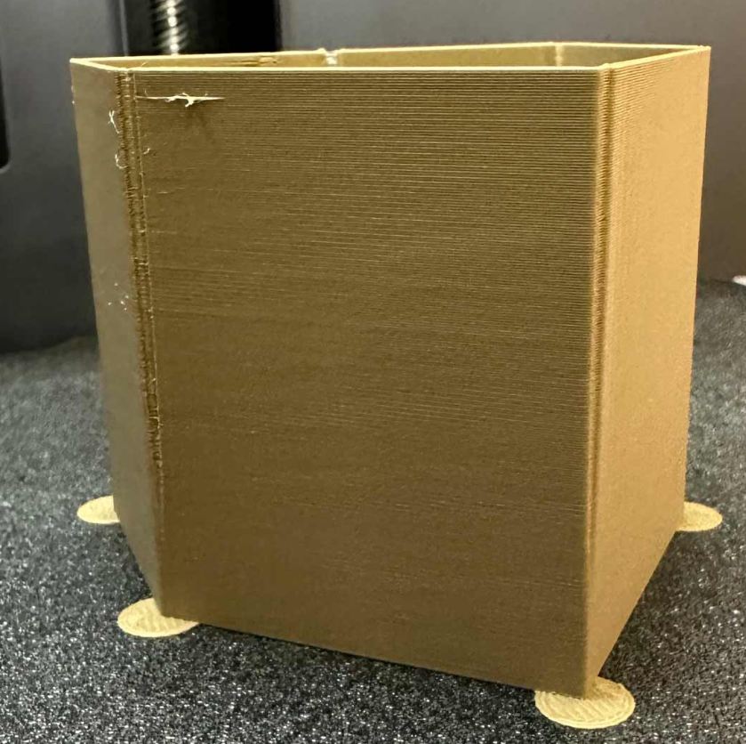
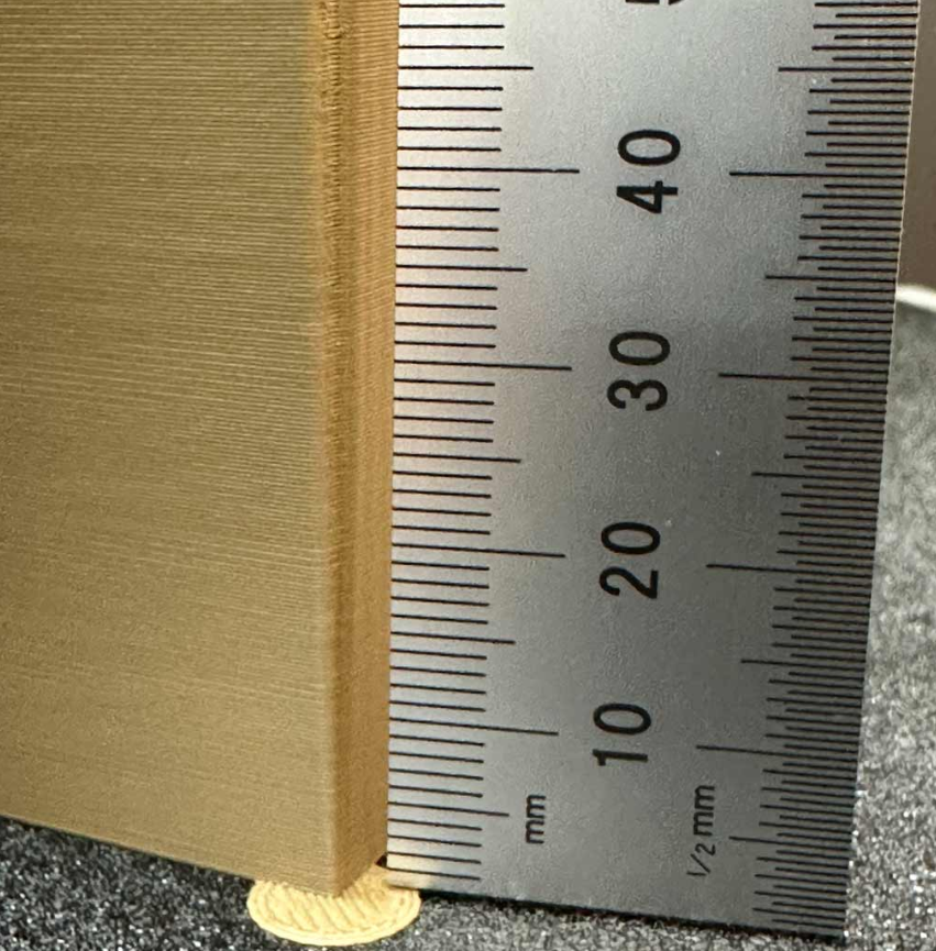
After printing is complete, observe each edge of the tower yourself and find the layer you consider to have the best overall quality.
Calculate the corresponding PA value. For example, based on the results shown in the image below, if the layer at 8mm height has the best quality, then the corresponding PA value is
0.002 x 8 = 0.016 (for Bowden extruders, it would be 0.16)
For detailed information, please visit the official website (https://gitee.com/n0isyfox/orca-slicer-docs/wikis/校准/压力提前)
¶ Flow Rate
Note: After completing calibration, please be sure to create a new project to reset the slicing software's state.
Flow Rate Calibration
Flow rate calibration is divided into two passes: coarse tuning and fine tuning. These two passes are almost identical in process except for the value range.
Perform flow rate calibration as follows:
- Select the printer, filament, and process you want to calibrate.
- Select
Coarse Tuningfrom the Calibration menu in the menu bar. - The software will automatically create a new project containing 9 calibration blocks, each of which will be printed with a different flow rate. Slice and print the project.
- Carefully examine the print results and select the block you consider to have the smoothest surface:
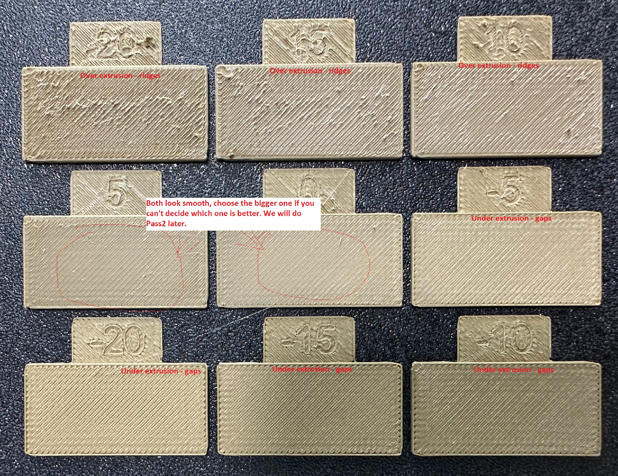
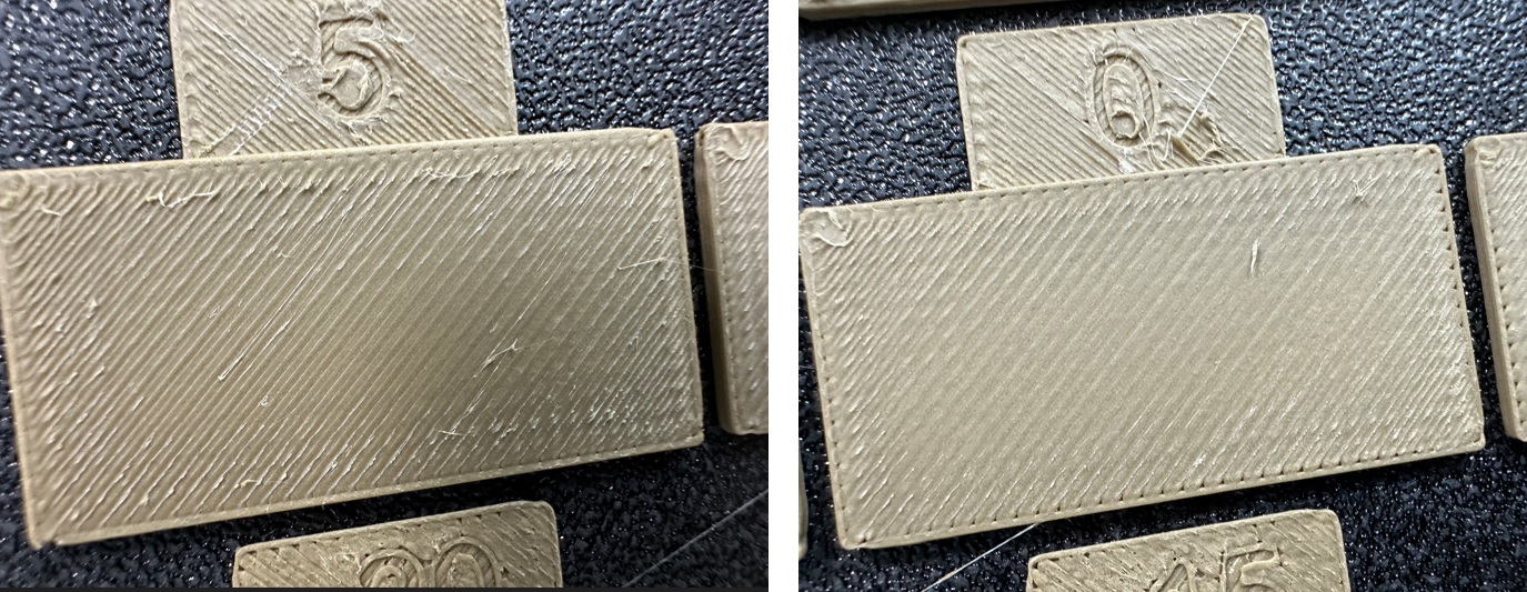
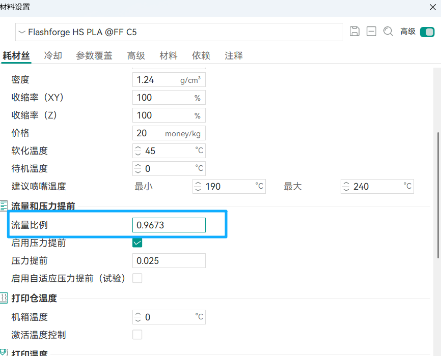
- Calculate the new flow rate ratio using the following formula: Current flow rate ratio x (100 + the number corresponding to the block with the smoothest surface) / 100. For example, if your current flow rate ratio in the filament settings is 0.98,
- And the number on the block with the smoothest surface is 5, then the new flow rate ratio is 0.98 x (100 + 5) / 100 = 1.029. Remember to save your filament settings after modifying the flow rate ratio!
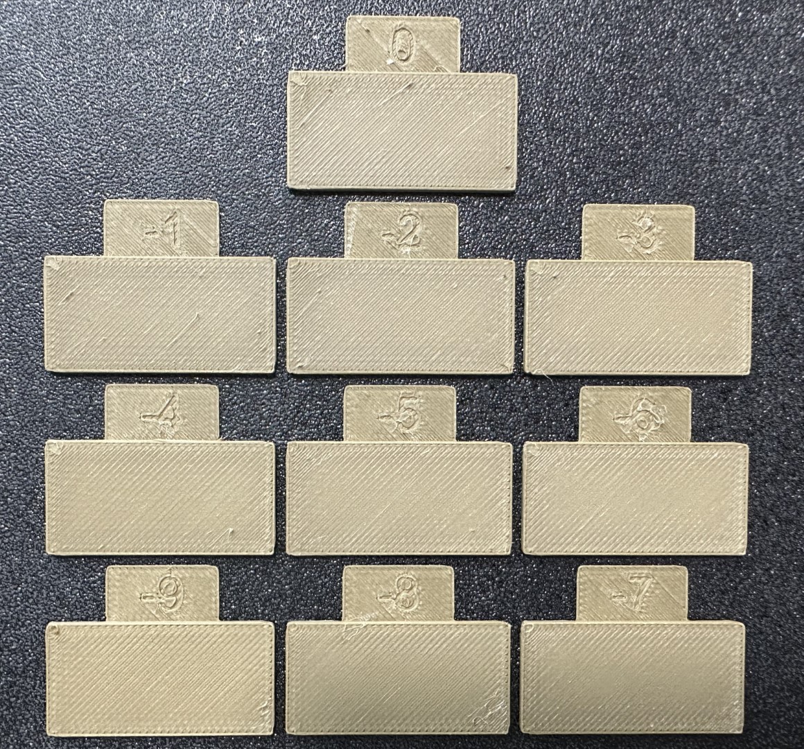
- Select Fine Tuning from the Calibration menu in the menu bar. The fine tuning process is similar to coarse tuning, except this time the project contains 10 blocks. Slice and print the project.
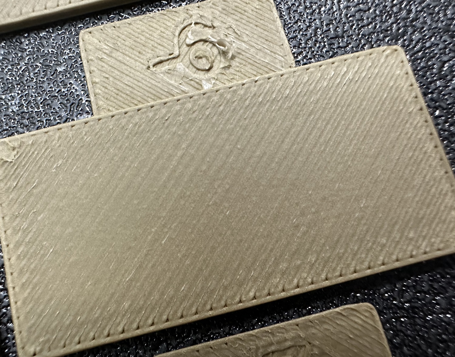
- Repeat steps 4 and 5. For example, if your flow rate ratio after coarse tuning is 1.029, and the number on the block with the smoothest surface during fine tuning is -6, then the final flow rate ratio is: 1.029 x (100 - 6) / 100 = 0.96726.
Once again, remember to save your filament settings!
For detailed information, please visit the official website (https://gitee.com/n0isyfox/orca-slicer-docs/wikis/校准/流量#流量校准)
¶ Retraction
Note: After completing calibration, please be sure to create a new project to reset the slicing software's state.
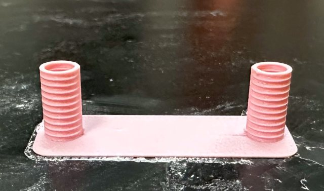
This test will automatically generate a retraction test tower. Different heights of the retraction tower use different retraction distances during printing, with a small bump at certain height intervals to distinguish them.
After printing is complete, we can carefully examine the results to determine the optimal retraction distance. The optimal retraction distance is typically the one corresponding to the layer with the least stringing. If multiple layers are equally clean, choose the one with the shortest retraction distance.
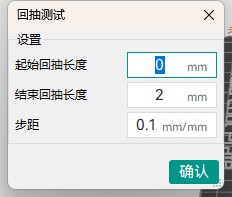
The dialog box shown in the image above allows you to adjust the test parameters, such as the starting and ending retraction lengths and the retraction length step. The default parameters start from 0mm with a 0.1mm step increment up to 2mm. For most direct drive extruders, these default parameters are sufficient. However, if you are using a Bowden extruder, you may need to change the parameters to start from 1mm with a 0.2mm step increment up to 6mm.
Note: When testing with filaments that are not prone to stringing, such as PLA or ABS, you may find that any amount of retraction works well, with the entire retraction tower showing no stringing from top to bottom. If this happens, simply set the retraction length in the filament settings to any value between 0.2mm and 0.4mm.
However, if you find severe stringing throughout the entire retraction tower from top to bottom, it usually means your filament is moist or your nozzle is leaking.
For detailed information, please visit the official website (https://gitee.com/n0isyfox/orca-slicer-docs/wikis/校准/回抽#回抽测试)
¶ Maximum Volumetric Speed
Note: After completing calibration, please be sure to create a new project to reset the slicing software's state.
Maximum Volumetric Speed Calibration
This test can be used to calibrate the maximum volumetric speed for a given filament. The preset maximum volumetric speed in Orca Slicer's built-in filament configurations may not be accurate enough. Using this test, you can calculate the maximum volumetric speed your actual filament can achieve.
To begin the test, you need to enter the following parameters: starting flow rate, ending flow rate, and step size. Typically, the default parameters (starting flow rate 5mm³/s, ending flow rate 20mm³/s, step size 0.5mm³/s) should be sufficient unless you have a rough idea of the possible flow rate range of your filament.
After the test model is printed, find the first layer from bottom to top where printing defects appear, paying special attention to the transition of wall texture from matte to glossy.
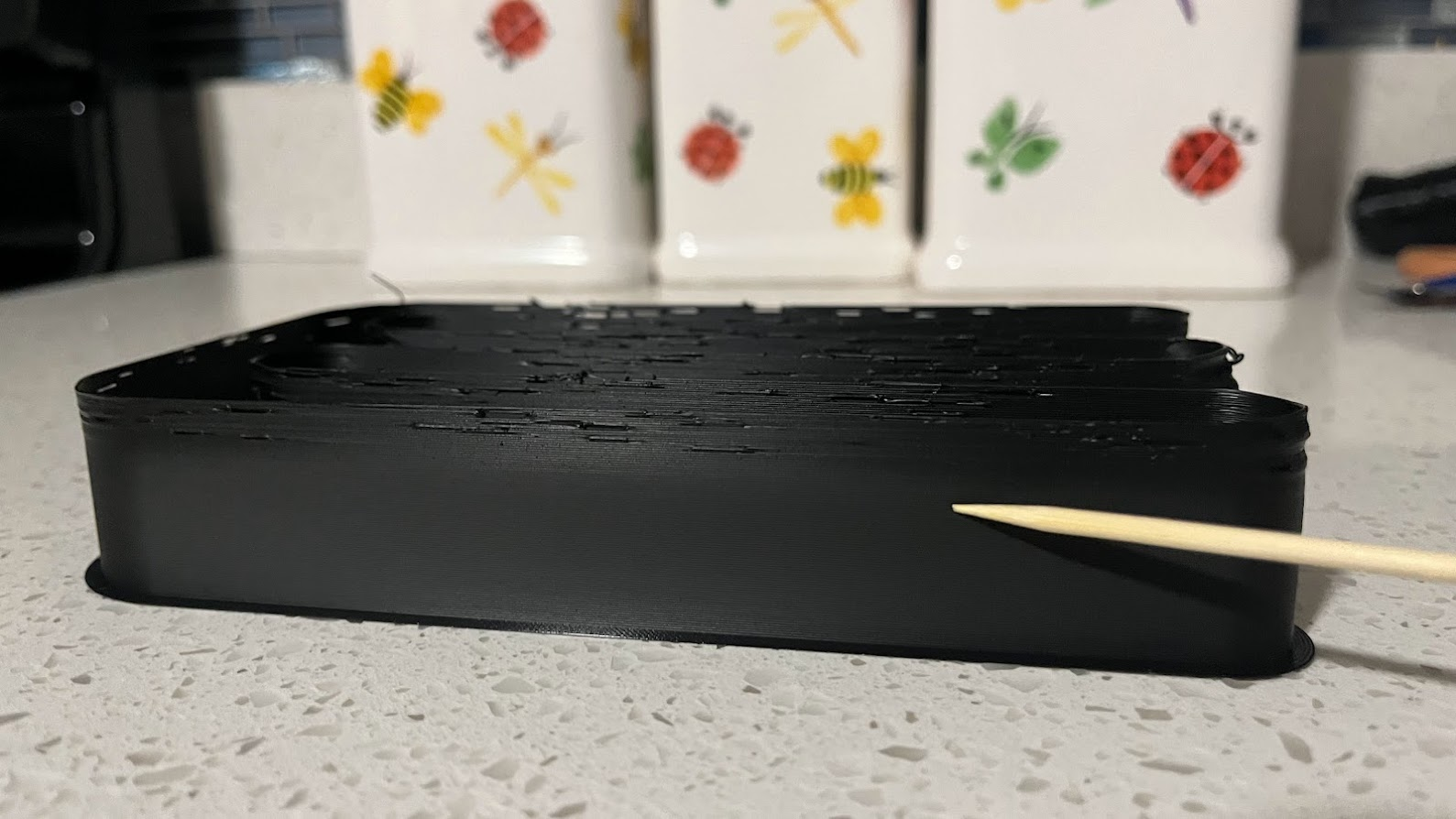
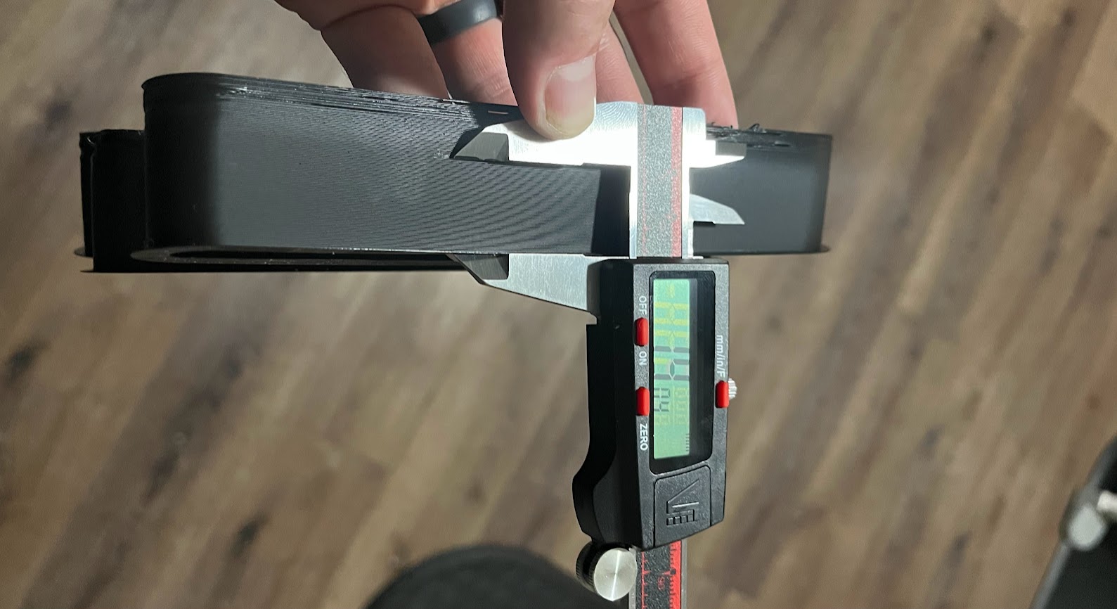
Use calipers or a ruler to measure the height of the first layer with printing defects from the bottom. Use the following formula to calculate the maximum volumetric speed of the filament: Starting flow rate + (height of first defect layer * step size). For example, if the test is performed with default parameters and the height of the first layer with printing defects is 19mm, then the corresponding maximum volumetric speed is 5 + (19 * 0.5), which is 13mm³/s. Enter this value in the maximum volumetric speed field in the filament settings.
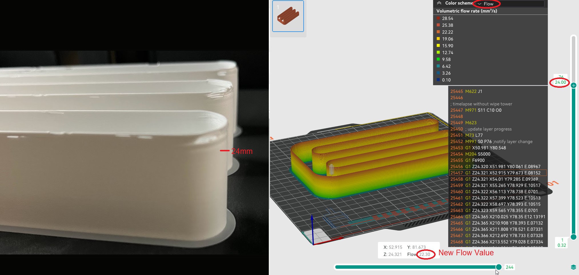
Alternatively, you can set the "Color Scheme" to "Flow" in Orca Slicer's "Preview" interface, then drag the scroll bar on the right to the first layer with printing defects, and drag the scroll bar at the bottom to display the printing flow rate used for that layer. This flow rate is the maximum volumetric speed for that filament:
Note: You may need to subtract 5-10% from your measured value to ensure print quality is not affected by measurement error.
For detailed information, please visit the official website (https://gitee.com/n0isyfox/orca-slicer-docs/wikis/校准/最大体积流量#最大体积流量校准)
¶ Wall Printing Order
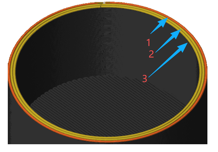
The order of printing inner walls (internal) and outer walls (external).
Inner Wall / Outer Wall
Using the Inner/Outer wall setting achieves the best overhang results. This is because overhang walls can attach to adjacent perimeters when printing. However, this option results in a slight decrease in surface quality, as the outer perimeter deforms when pressed against the inner perimeter.
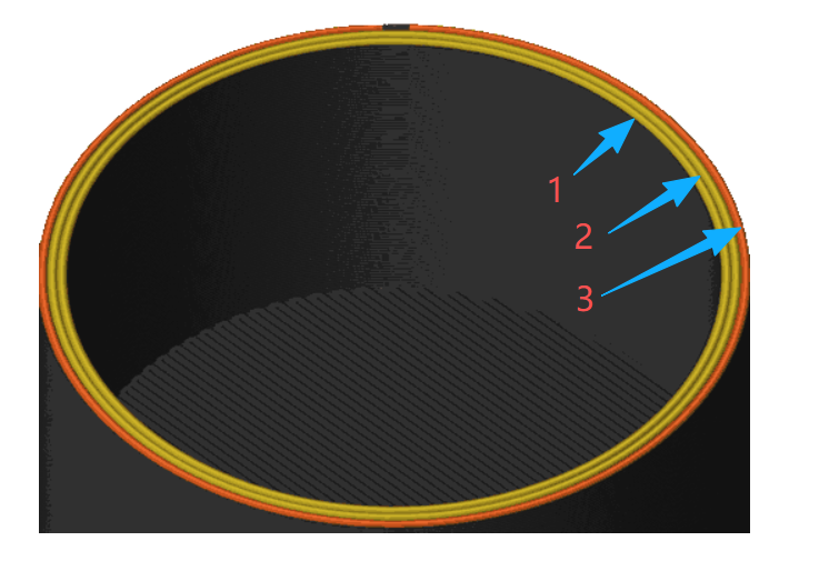
Inner Wall / Outer Wall / Inner Wall
Using the Inner/Outer/Inner method achieves the best outer surface finish and dimensional accuracy, as the outer wall is printed without interference from inner perimeters. However, overhang performance is reduced because there are no inner perimeters to serve as support for the outer wall printing. This option requires at least 3 wall layers to be effective, as it first prints the inner wall starting from the 3rd perimeter, then the outer perimeter, and finally the first inner perimeter. In most cases, this option is recommended over the Outer/Inner option.
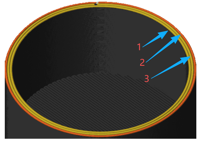
Outer Wall / Inner Wall
Using Outer/Inner achieves the same outer wall quality and dimensional accuracy advantages as the Inner/Outer/Inner option. However, the Z seam may appear less consistent since the first extrusion of a new layer starts from the visible surface.
¶ Arc Fitting
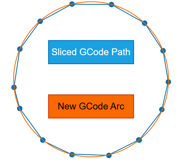
When enabled, this feature uses G2 and G3 to replace many short linear movements (G1 segments) with fewer arc commands.
Arc fitting primarily changes how toolpaths are encoded in G-code. It may be beneficial in certain workflows, but it is not a quality-improving feature.
Important Notes
Make sure your printer supports G2/G3 commands!
Advantages
- Smaller G-code files:
- Faster upload speed.
- Less storage space required.
- Reduces read/write operations in memory and extends the limited write lifespan (TBW) of SD cards.
- Fewer moves for the firmware planner to process:
- Helps slower controllers when performing concurrent tasks such as saving state for power-loss recovery.
- Helps with limited connectivity.
- Smoother curves when using low-polygon models.
Disadvantages / Risks - Compatibility varies: some firmware ignores G2/G3.
- Arcs introduce approximations: Converting segments → arcs in OrcaSlicer and arcs → segments in firmware may slightly alter the path.
- Final smoothness depends on the firmware's arc segmentation resolution; coarse settings may make curves appear angular.
- Arc-to-segment conversion increases the printer's CPU load, which may cause slowdowns (and reduced surface quality) on older/8-bit microcontrollers.
Additionally, modern STL files typically have higher resolution than slices generated by most printer firmware.
Tip
For Klipper printers, please refer to the documentation for supporting G-code arc (G2/G3) commands to set the resolution of internally generated arcs: the default value is 1.0mm per segment, which is very coarse.
Note
Converting arcs to internally generated segments requires more CPU resources from the printer microcontroller, which may cause slowdowns (and reduced surface quality) on printers using 8-bit microcontrollers.
¶ Elephant Foot Compensation
This feature compensates for the "elephant foot" effect, which occurs when the first few printed layers are wider than the remaining layers due to:
- The weight of the material above them.
- Thermal expansion of the material.
- Excessive bed temperature.
- Inaccurate bed height/leveling.
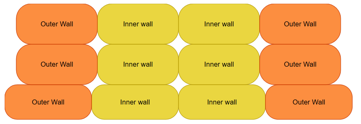
To mitigate this effect, OrcaSlicer allows you to specify a negative distance that will be applied to the specified first few layers. This adjustment effectively reduces the width of the first few layers, helping to achieve more accurate final print dimensions.
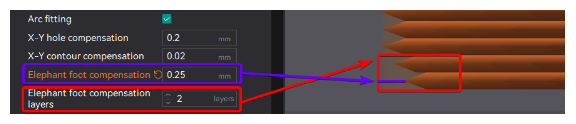
The compensation works as follows:
Current layer <= Input compensation layers
Compensation = Input compensation distance - (Input compensation distance / input_compensation_layers) × (Current layer - 1)
Based on this equation, we can establish the following rules:
- At the first layer, since layer 1 - 1 = 0, the compensation rate is 100%.
- Intermediate layers (between the first layer and the input compensation layers) will have linear compensation applied.
- Layers exceeding the specified number will not be compensated.
Assuming a compensation value of 0.25mm:
Elephant foot compensation layers = 1:
- First layer: 0.25mm compensation (100%)
- Second layer and above: No compensation (0mm)
Elephant foot compensation layers = 2: - First layer: 0.25mm compensation (100%)
- Second layer: 0.25 - (0.25 / 2) × (2 - 1) = 0.125mm compensation (50%)
- Third layer and above: No compensation (0mm).
Elephant foot compensation layers = 5: - First layer: 0.25mm compensation (100%)
- Second layer: 0.25 - (0.25 / 5) × (2 - 1) = 0.2mm compensation (80%)
- Third layer: 0.25 - (0.25 / 5) × (3 - 1) = 0.15mm compensation (60%)
- 4th layer: 0.25 - (0.25 / 5) × (4 - 1) = 0.1mm compensation (40%)
- 5th layer: 0.25 - (0.25 / 5) × (5 - 1) = 0.05mm compensation (20%)
- 6th layer and above: No compensation (0mm).
Note
This feature will make the part's footprint on the build plate appear smaller in the preview, but the final print (if calibrated correctly) will have the correct dimensions after slicing.
This is why the skirt may appear separated from the object when this feature is enabled. However, in the final print, the skirt will be properly attached to the object.
If you set a high value for the elephant foot compensation distance, you may need to enable the "Skirt uses EFC profile" option to ensure the skirt attaches properly.
¶ Overhang Speed Reduction
Enabling this option reduces print speed for different overhang angles. This helps improve print quality and reduces issues such as stringing or sagging.
¶ Corner Speed Reduction
Enabling this option slows down print speed in areas where edges may curl upward. For example, when printing overhangs at sharp corners like the front of a Benchy hull, it slows down further to reduce curling that is exacerbated by multi-layer accumulation.
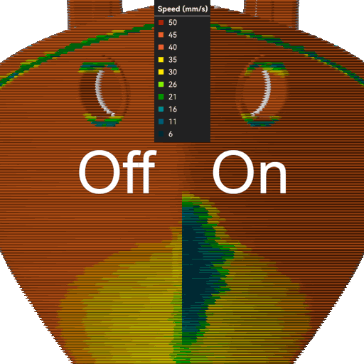
It is generally recommended to enable this option unless your printer's cooling capability is sufficient or the print speed is slow enough that edge curling does not occur. If printing at a high outer perimeter speed, this parameter may produce slight artifacts when decelerating due to the large change in print speed. If you notice artifacts, make sure your pressure advance is properly tuned.
Note
When this option is enabled, overhang perimeters will be treated as overhang sections, meaning the overhang speed will be applied even if the overhang perimeter is part of a bridging section. For example, when a perimeter is 100% overhang with no wall support below, 100% of the overhang speed will be applied.
¶ Object Exclusion
This feature applies to printing multiple models. Its purpose is to allow users to conveniently select which models to exclude when one or more models fail during printing, ensuring that the remaining models can print normally.
Slicing Settings
1. First, enable the "Advanced" option in the "Process" panel. Then, check the "Object Exclusion" option on the "Others" page.

2. Slice and print
Printer Settings
¶ 1. After printing starts, the Object Exclusion [ ] key will appear on the screen. Tap it as needed.
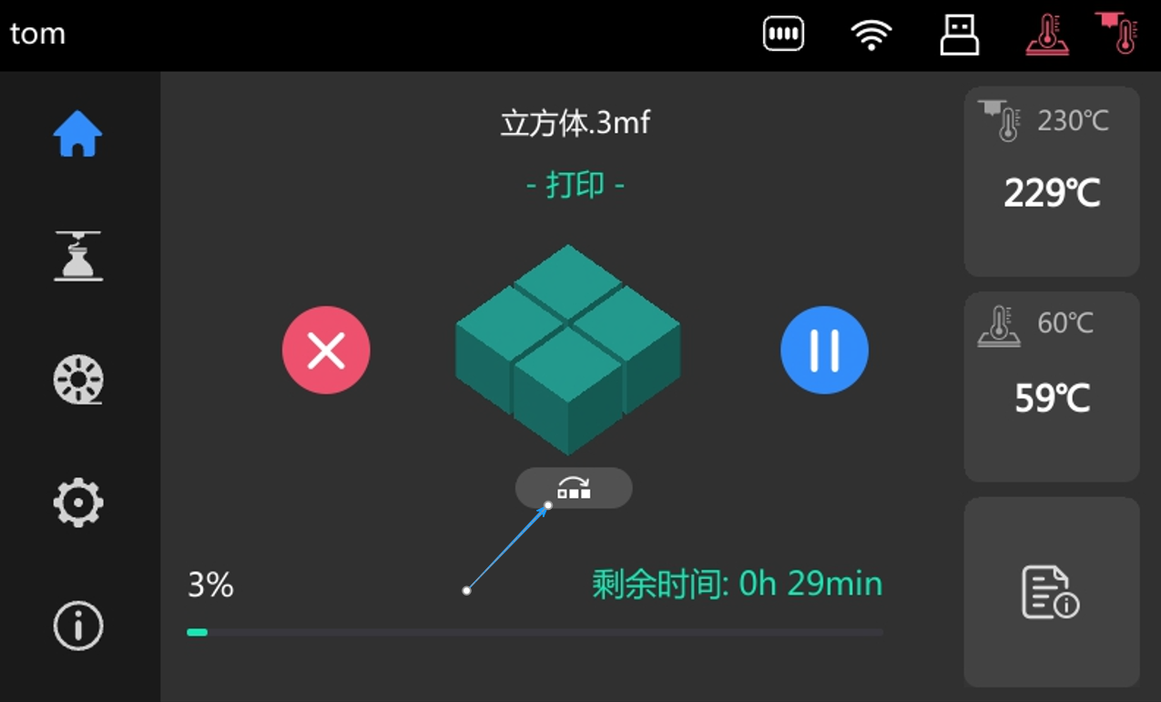
¶ 2. Tap [] to enter the "Object Exclusion" interface. Please refer to the following images for the operation steps:
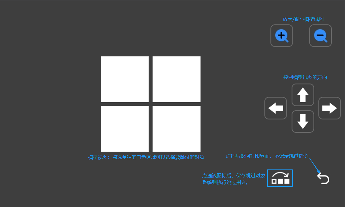
¶ 3. Select the model to exclude from printing.
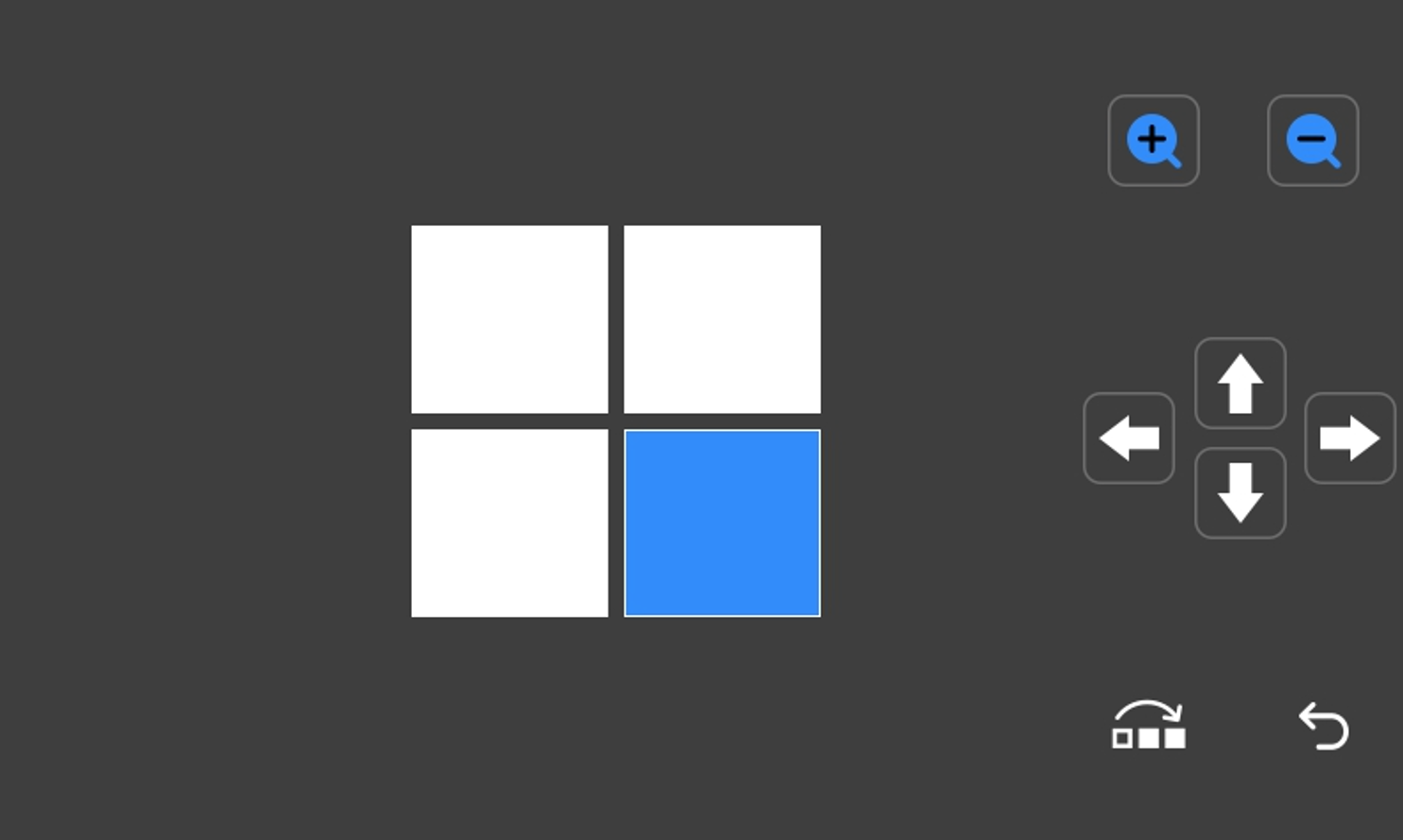
a. Select the model view, tap the model to exclude, and the selected block will be displayed in blue. Tap [] to apply this function.
b. If you tapped the wrong area when selecting the model, you can tap [ ] again to reset.
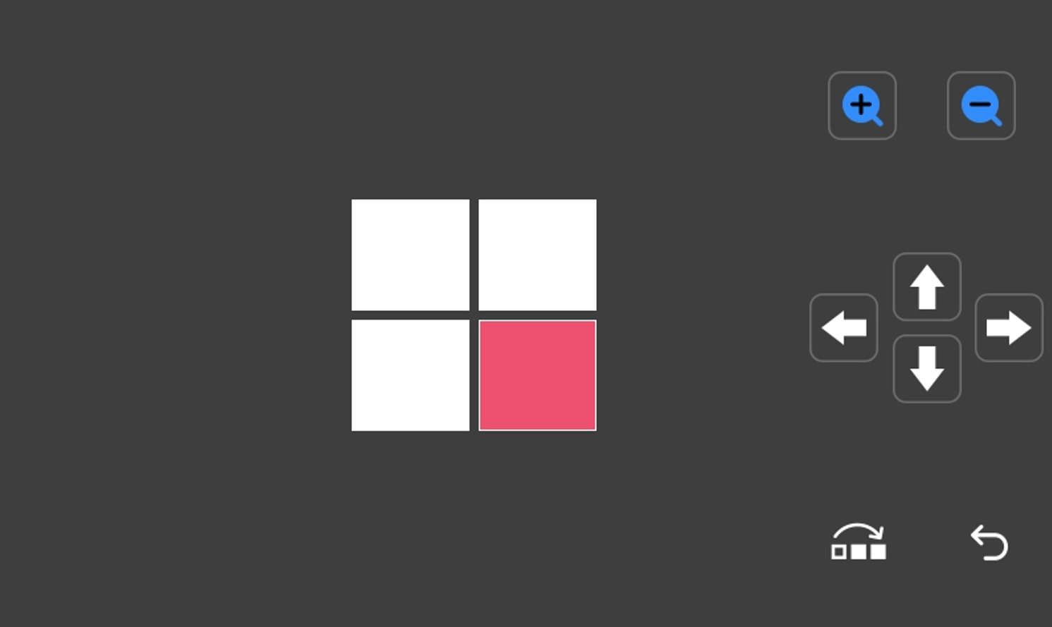
c. After saving successfully, the excluded area will be displayed in red.